
As of 2025, the UK is one of the top users of Autodesk Revit, with 998 users making up 10.07% of the global customer base. This shows how important Revit is for designing and managing building projects. A big part of using Revit effectively is organising your project with different views.
Views like floor plans, sections, elevations, 3D views, and schedules help you present your design clearly. But before creating views, it’s important to set up your project properly to keep everything consistent and easy to manage.
In this article, you’ll learn about different types of views in Revit, including drafting, section, and perspective views, along with tips on customising view properties for clarity. In addition, you’ll also learn how to use schedules to manage and organise views efficiently.
Drafting View vs. Detail View in Revit
Drafting Views are separate from the model, meaning they don’t change when the model updates. They are helpful in adding general details, standard notes, or imported CAD drawings that you can use in different projects.
Detail Views, however, are tied to a specific part of the model. They let you zoom in on a section, elevation, or plan and add extra construction details.
Knowing the difference between Drafting Views and Detail Views helps you create clear and effective project documentation. Below are the differences between the two:
| Features | Drafting Views | Detail Views |
| Purpose | Used for creating 2D views such as details, legends, and annotations. | Used for showing detailed representations of parts or assemblies from a specific view or section. |
| Scope | Entirely 2D, not linked to the 3D model. | Typically a portion of a larger model, often from a section or elevation. |
| Link to Model | No link to the 3D model; only 2D elements can be added. | Linked to the 3D model and may include model elements. |
| View Depth | No depth; all elements are represented flat and in 2D. | Shows depth and includes 3D model elements, often with a focus on specific parts. |
| Visibility of Model Elements | No visibility of actual model elements unless manually drawn. | Model elements are shown with the option to hide or modify certain aspects. |
| Usage | Used for detailing, annotations, and creating graphical representations of non-model elements. | Used for focusing on detailed parts of the building or object, and they show components from the model. |
| Creation | Created by users from scratch; independent of the project model. | Automatically generated based on section views or selected areas of the model. |
| View Scale | Usually does not have a scale or fixed scale; it’s more flexible for drawing at different scales. | Has a fixed scale that matches the part of the model being detailed. |
| Update with Model Changes | Does not update automatically when the model changes; requires manual adjustment. | Automatically updates when changes to the model are made within the viewable area. |
| Annotation | Supports extensive annotation, including text, symbols, and dimensions. | Allows annotation of the model and detail elements, but annotations are often restricted to the detailed parts. |
| Placement in Project | Can be placed in the project without being associated with any view of the model. | Linked directly to the specific area of the model from which it was created. |
While both are used to add detailed information to a project, they serve different purposes. To make the most of these views, proper preparation is key.
Setting up for View creation in Revit
Before creating views in Revit, proper planning is important for clear and accurate project documentation. Whether you’re working on floor plans, sections, elevations, or 3D views, organising your model can save time and prevent mistakes.
This means setting up view templates, adjusting visibility settings, defining levels and grids, and ensuring the right worksets are active. A well-structured approach helps create views that clearly show the design while keeping everything consistent across the project.
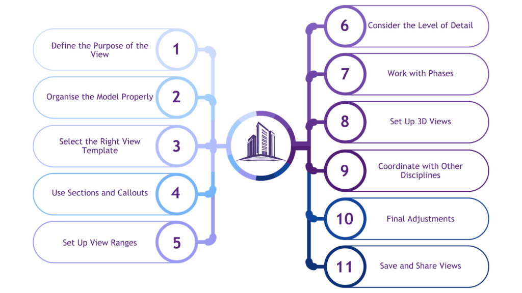
Before creating views in Revit, it’s important to follow key steps to ensure they are clear, accurate, and well-organised. Below are the key steps:
- Define the Purpose of the View
Start by identifying the type of view you need, such as a floor plan, section, elevation, 3D view, or detail view. Each type serves a different purpose, so choosing the right one ensures clarity.
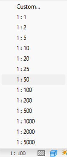
Next, consider the scale of the view. Larger scales, like 1:50 or 1:20, are best for detailed views, while smaller scales, like 1:100 or 1:200, work well for overall floor plans or elevations.
- Organise the Model Properly
A well-structured model helps in creating accurate and clear views. Ensure all elements are placed correctly within their respective phases, levels, and grids. Levels and grids act as the backbone of the model, so double-check their alignment before generating views.
Also, manage visibility settings to prevent unnecessary clutter by filtering out elements like furniture, annotations, or structural components that are not needed.
- Select the Right View Template
View templates help maintain consistency across similar views. If you’re working on multiple floor plans or sections, applying a template ensures uniform settings for visibility, annotations, and graphic styles. Revit provides built-in templates such as Architectural, Structural, and MEP-F, but you can customise or create new ones based on your needs.
- Use Sections and Callouts
Sections provide a closer look at specific areas within a floor plan, making them useful for detailed analysis. Plan where to place section markers to ensure a logical flow. Callout views are another way to zoom in on specific details, often used when you need a more focused view of a certain portion of the design.
- Set Up View Ranges
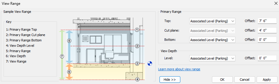
For floor plans, adjusting the view range determines which elements are visible based on their elevation. Fine-tuning the top, bottom, and cut planes of the view range ensures that only the necessary components are displayed.
Additionally, adjusting visibility settings allows you to control whether ceilings, floors, or other elements appear in the view.
- Consider the Level of Detail
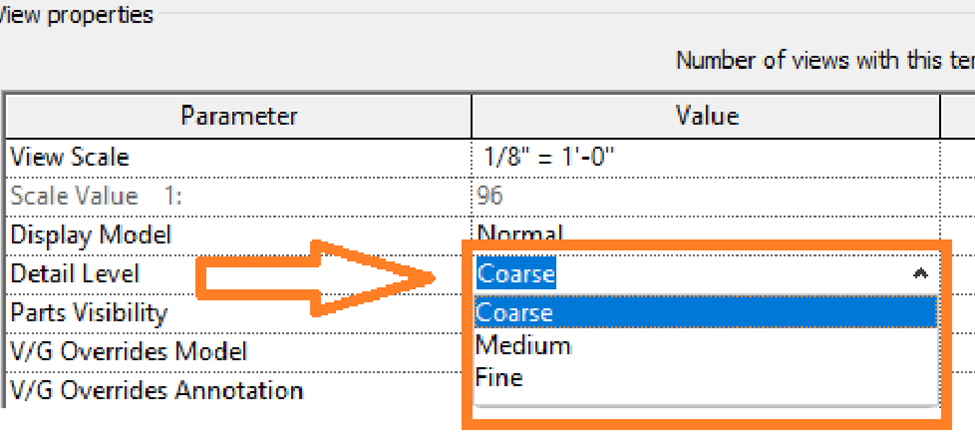
Each view should have an appropriate level of detail. Revit provides three detail levels: Coarse, Medium, and Fine. For example, a general floor plan may only need a Coarse setting, while a detailed section view may require Fine detail.
Additionally, include necessary annotations such as dimensions, tags, and text notes to improve clarity.
- Work with Phases (If Applicable)
If the project involves different construction phases, such as existing conditions, demolition, or new construction, set up the phase settings accordingly. This ensures that each view reflects the correct stage of the project.
- Set Up 3D Views (If Necessary)
3D views provide a better understanding of the design. Decide whether you need a perspective or an orthographic view. Perspective views are helpful for presentations, while orthographic views offer accurate, scaled representations. If creating perspective views, position cameras at the right locations to capture the desired angles.
- Coordinate with Other Disciplines
Collaboration is key in Revit, especially when working with multiple disciplines like architecture, structure, and MEPF. Ensure all models are properly linked, and elements from different disciplines align correctly. Regular coordination with team members helps maintain consistency across views.
- Final Adjustments
After setting up the views, review visibility and graphic settings to confirm that the necessary elements are displayed. Use the crop region tool to refine the boundaries of the view, keeping the focus on important details while eliminating unnecessary areas. Lastly, ensure the view is clean, uncluttered, and understandable.
- Save and Share Views
Once satisfied with the views, save them with clear naming conventions for easy reference. If needed, share the views with team members by placing them on sheets or exporting them in formats like PDF or DWG for better accessibility.
Following these steps allows you to create well-structured, clear, and effective views in Revit, making the modelling process more efficient and organised.
A well-structured view setup improves clarity and simplifies the modelling process. In some cases, you may need to create details that aren’t directly tied to the model itself. This is where Drafting Views come in.
Also read: 11 Steps to Create Revit Dynamo Scripts for Beginners.
Creating a Drafting View in Revit
A drafting view in Revit is a 2D view that stands alone and isn’t linked to the model. It’s great for adding standard details, notes, or imported drawings. Unlike detail views, which focus on specific parts of the model, drafting views can be reused in different projects, keeping your documentation consistent.
Whether you need to show construction details, typical connections, or standard symbols, learning how to create and manage drafting views will help you stay organised and work more efficiently.
To create a drafting view in Revit, follow these steps:
- Open Your Project
Make sure your Revit project is open since the drafting view will be created within it.
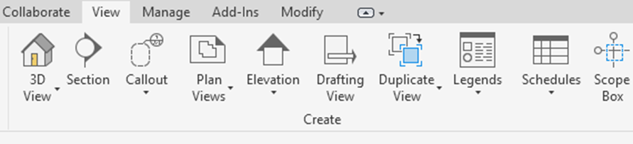
- Go to the View Tab
On the Ribbon, click on the View tab.
- Select Drafting View
In the Create panel, click Drafting View. Alternatively, you can right-click in the Project Browser and select New Drafting View.
- Name Your Drafting View
Revit will prompt you to name the new view. Choose a clear and relevant name, like Wall Details or Floor Plan Legend. Click OK to confirm.
- Use Drawing Tools
Once the drafting view is open, you can use various 2D drawing tools, such as:
- Lines: To create shapes and details.
- Text: To add notes or descriptions.
- Dimensions: To show measurements.
- Detail Components: To insert pre-made elements from Revit’s library.
- Symbols: To include standard symbols like doors or plumbing fixtures.
- Organise Your Elements
Use tools like Align, Trim/Extend, and other modification options to adjust and refine your drawing.
- Review and Adjust
Zoom in, zoom out and pan around to check your drafting view. Since it’s a 2D-only view, any changes made here won’t affect your 3D model.
- Add the Drafting View to a Sheet
In the Project Browser, locate your drafting view and drag it onto a sheet. Adjust its scale and position as needed for a clear presentation.
Once the drafting view opens, you’ll see a blank canvas. You can now add 2D details using lines, text, and symbols to improve your drawings. To use them effectively, you need to follow some tips.
Ready to simplify your projects and achieve the benefits?
BIM ASSOCIATES is your one-stop BIM Solution provider for Revit Architectural and Structural Solutions. They coordinate with your team to develop, record, and streamline the BIM Revit Model, along with the sheets, Bill of Quantities, Bill of Materials, and clash coordination.
Tips for Using Drafting Views Effectively
When you open a drafting view, you begin with a blank canvas, allowing you to add 2D details to improve your drawings. It’s essential to use the right tools and keep everything well-organised to get the best results. Clear annotations, neat layouts, and consistent styling will make your drawings easier to read and look more professional.
Below are some simple tips to help you make the most of drafting views:
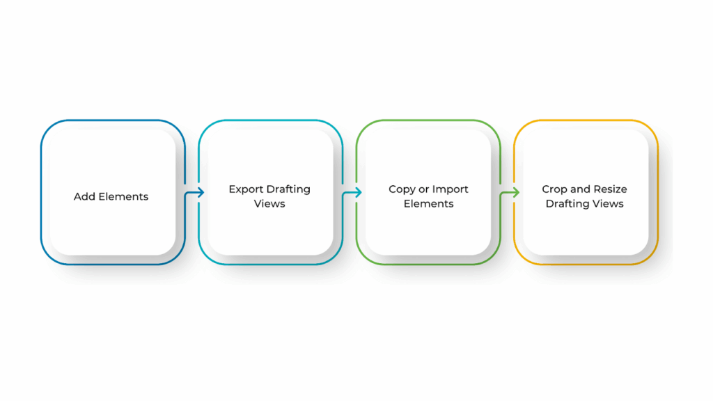
- Add Elements
You can add and edit elements in a drafting view using the same tools available in other 2D views. To get started, go to the Annotate tab, where you’ll find tools for drawing shapes and adding text, tags, and dimensions. These tools help you create clear and detailed drawings without affecting the model.
- Export Drafting Views
If you need to share a drafting view or use it in another project, you can export it as an image or CAD file. Follow these steps:
- In the Project Browser, right-click the drafting view.
- Click Save to New File to export it.
- Open the project where you want to use the drafting view.
- Go to the Insert tab, then click Insert From File under the Load from Library panel.
- Select the file that contains the drafting view and click OK.
The copied view will now appear in your list of drafting views. You can also copy entire sheets of drafting views, as well as schedules, using this method.
- Copy or Import Elements
If you want to reuse elements from another view or project, you can either copy or import them into your drafting view.
Select the 2D elements and use Ctrl+C (Copy to Clipboard) and Ctrl+V (Paste) from the Modify tab to copy elements from another view within the same project.
To import elements from another file, such as a DWG or PDF, go to the Insert tab and use the Link CAD option. This allows you to transfer views between projects or save an existing view as a CAD file and import it into a drafting view, keeping it separate from the model.
- Crop and Resize Drafting Views
Drafting views cannot be cropped because they are not tied to a specific model space. However, you can control their size on sheets by adjusting the scale. Changing the scale ensures the drafting view fits well within your layout while maintaining clarity.
While Drafting Views are helpful for independent details, Section Views provide a deeper understanding of the model by cutting through elements to reveal hidden components.
Creating Section Views in Revit
Section views in Revit help you see inside your building design by cutting through the model to show interior details. They are useful for architects, engineers, and contractors to understand how various parts of the building connect, including structural elements, material layers, and spaces.
Using Revit’s Section tool, you can create accurate cut-throughs of walls, floors, and other components. You can also adjust visibility settings to highlight important details as needed.
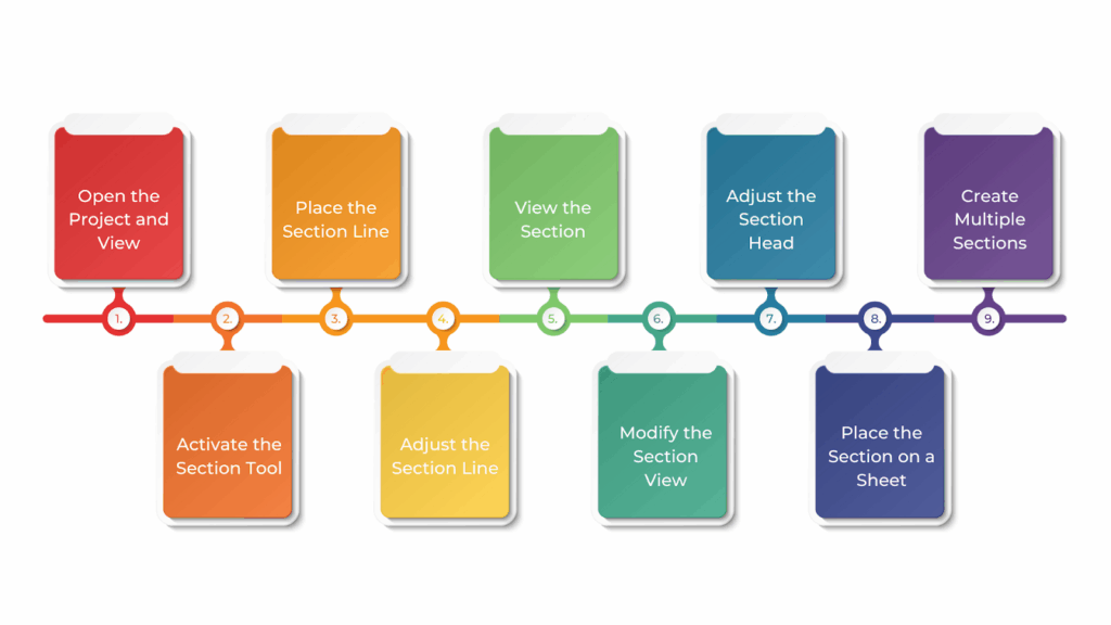
To create section views in Revit, follow these steps:
- Open the Project and View
Make sure your project is open in Revit. Go to the View tab on the ribbon and open a 2D view, such as a floor plan, where you want to create the section.
- Activate the Section Tool
In the View tab, under the Create panel, click on the Section tool. It is also accessible from the Quick Access Toolbar by clicking on the Section icon.
- Place the Section Line
After selecting the Section tool, your cursor will change to a section line symbol. Click in the drawing area to set the starting point of the section, then drag to define the endpoint. This determines which part of the model will be cut through. You can place the section line horizontally, vertically, or at an angle, depending on how you want to view the cut.
- Adjust the Section Line
Once placed, you can move, rotate, or resize the section line by dragging its endpoints or center. You can also flip the section direction using the flip arrows at the ends of the line to change which side of the model is visible in the section view.
- View the Section
Revit automatically generates a section view, which you can find in the Project Browser under Views. The section is named based on its order (e.g., Section 1, Section 2). To open the section, double-click on it in the Project Browser. The section view will display a cut-through of the model, showing internal elements at the section line’s location.
- Modify the Section View
You can adjust how much of the model is visible in the section:
- Section Depth: Change this in the Properties palette to control how far in front and behind the section line the view extends.
- Visibility and Graphics: Modify which elements (e.g., walls, floors, columns) are visible using the Visibility/Graphics settings in the View Control Bar or Properties palette.
- View Range: Adjust the view range to control which objects above or below the cut plane appear in the section view.
- Adjust the Section Head (Optional)
The section head (arrow that indicates the view direction) can be modified for clarity. Select the section line and click Edit Type in the Properties palette to adjust properties like the Arrowhead and Text Label.
- Place the Section on a Sheet (Optional)
For documentation, you can add the section view to a sheet. Open a Sheet view, then drag the section view from the Project Browser onto the sheet. Adjust its size and placement as needed.
- Create Multiple Sections (Optional)
For complex designs, you may need multiple sections to capture all necessary details. Repeat the steps above to create additional sections at different locations in your model.
These steps will help you create, customise, and organise section views efficiently in Revit. Once your section views are in place, refining their appearance and settings can make them even more effective.
Customizing Views Properties in Revit
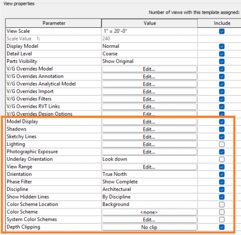
In Revit, you can adjust view properties to control how your drawings look. Changing settings like scale, detail level, visibility, and graphics helps you create clear and well-organised views that fit your project’s needs.
This improves clarity, presentation, and organisation. These adjustments ensure that all necessary elements are visible while keeping the view clean and understandable.
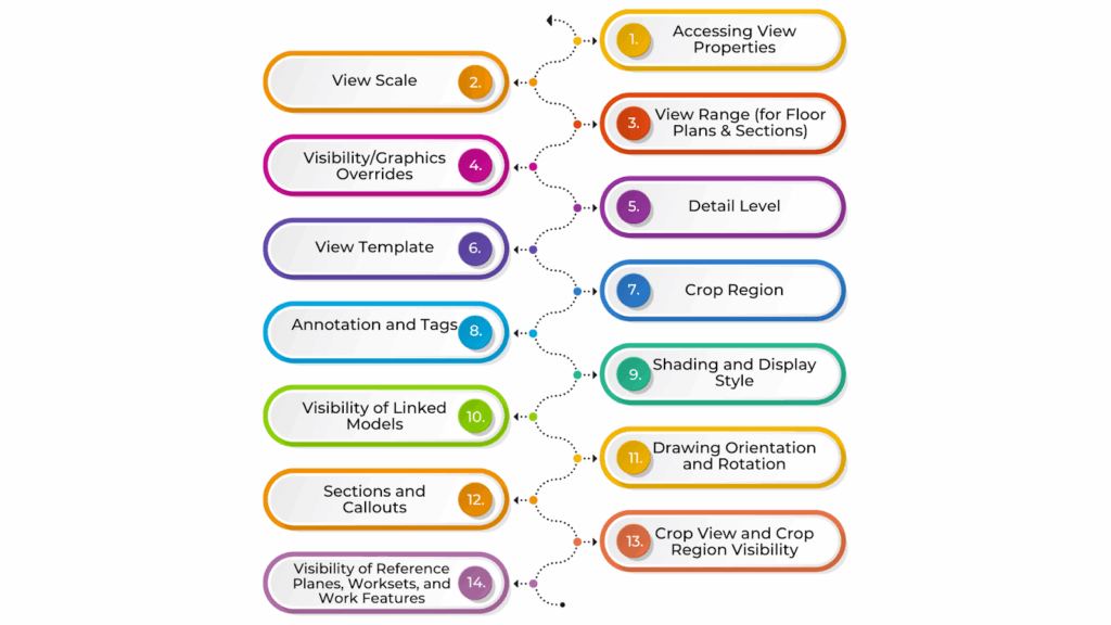
Below are key ways to customise view properties in Revit:
- Accessing View Properties
To change view properties, right-click the view in the Project Browser and select Properties. Alternatively, if the view is open, use the Properties palette on the left side of the screen. If the palette is not visible, go to the View tab > User Interface > Properties to enable it.
- View Scale
The scale determines how the view is represented. Larger areas use smaller scales (e.g., 1:100), while detailed views use larger scales (e.g., 1:20). To adjust the scale, open the Properties palette, find Scale, and select the appropriate option. You can also create custom scales by clicking Edit next to the scale dropdown.
- View Range (for Floor Plans & Sections)
The view range defines which elements are visible based on their elevation. In the Properties palette, scroll to View Range and click Edit. Adjust the Top, Cut, and Bottom planes to control what is shown. The View Depth setting allows additional control over what appears below the cut plane.
- Visibility/Graphics Overrides
This setting controls what elements are visible and how they appear. Select the view and go to the View tab > Visibility/Graphics (or press VG). In the Overrides dialog box, you can turn categories (e.g., walls, doors) on or off, change colours, adjust transparency, and modify line styles.
- Detail Level
The Detail Level determines how much detail is shown. In the Properties palette, choose Coarse (simplified view), Medium (moderate detail), or Fine (detailed view). This helps control the level of detail needed for each drawing.
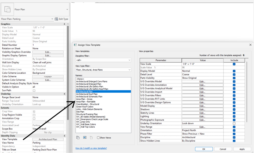
- View Template
View templates ensure consistency across multiple views. In the Properties palette, find View Template and select a template. If no template is assigned, click Apply Template to choose one or create a custom template in the View Template dialog box.
- Crop Region
The crop region defines what portion of the model is visible in a view. Click Crop Region in the View tab, then resize or move it to focus on a specific area. You can adjust the crop region’s visibility and style in the Properties palette > Visibility/Graphics settings.
- Annotation and Tags
Annotations like dimensions, text notes, and tags help add information to views. In the Properties palette, you can control annotation visibility and scale. You can also turn tags on or off based on project needs.
- Shading and Display Style
These settings control how the model appears visually. In the Properties palette, find Shading and Display Style and choose:
- Wireframe (no shading)
- Hidden Line (solid elements without shading)
- Shaded (adds shading for better visualisation)
- Realistic (displays materials and lighting effects)
- Visibility of Linked Models
If your project includes linked models (e.g., architectural, structural, MEP-F), you can manage their visibility in each view. Go to Visibility/Graphics Overrides, where you can show, hide, or apply a specific view template to linked models.
- Drawing Orientation and Rotation
Adjusting view orientation ensures correct positioning on sheets and presentations. Use the Rotate tool in the View tab to change the view’s direction.
- Sections and Callouts
Sections and callouts allow you to zoom into specific areas for more detail. Use the Section tool to define a cut plane. For detailed zoom-in views, use Callouts, which generate new views that can be customised separately.
- Crop View and Crop Region Visibility
The Crop View setting limits what is visible in a drawing, while the Crop Region defines the boundary. Enable or disable the crop region in the Properties palette and adjust its visibility in the Visibility/Graphics settings.
- Visibility of Reference Planes, Worksets, and Work Features
Reference planes and worksets help with project coordination. In Visibility/Graphics settings, you can choose whether to display them. These elements are useful during design but may not be necessary in the final construction view.
Customising these properties can improve clarity, consistency, and organisation in your Revit drawings. In addition to customising view properties, working with perspective views can provide a more effective and realistic representation of your model.
How to Set Your Autodesk Revit Perspective View?
Setting up a perspective view in Autodesk Revit helps you create realistic 3D visuals of your model, making it easier to understand spaces and present designs clearly. Unlike orthographic views, perspective views add depth and a more natural appearance, which is especially useful for client presentations and design reviews.
To get the best results, you’ll need to adjust the camera position, field of view, crop boundaries, and visual styles. Knowing how to fine-tune these settings will help you create accurate and engaging project visualisations.
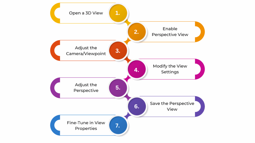
To set a Perspective View in Autodesk Revit, follow these steps:
- Open a 3D View
To create a perspective view, you first need to be in a 3D view. You can do this by selecting 3D View from the View tab on the ribbon or opening an existing 3D view from the Project Browser.
- Enable Perspective View
Revit’s 3D views are orthographic by default, meaning they do not show depth. To switch to a perspective view, open the View Control Bar at the bottom of the drawing window.
Look for the Perspective checkbox on the far-left side. If this box is unchecked, your view remains orthographic. Once you check it, the view will switch to perspective, where objects appear smaller as they move further away, creating a realistic depth effect.
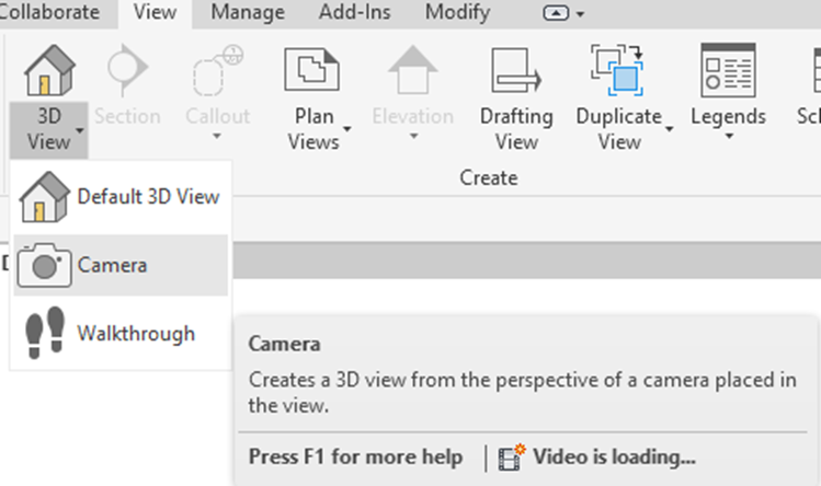
- Adjust the Camera/Viewpoint
For better control over your perspective, use the Camera tool. Go to the View tab, click on Camera (under the Create panel), and place the camera by clicking once to set its position. Click again to define the target point the camera should focus on. This will create a perspective view.
Once the camera is placed, you can adjust its position and angle by selecting and dragging its symbol in the drawing area. This helps fine-tune the viewpoint to achieve the desired perspective.
- Modify the View Settings (Optional)
After creating the perspective view, you can refine it further. Adjust the Field of View (FOV) by selecting the camera view and dragging the near and far clipping planes to control how much of the model is visible. Additionally, you can modify the View Range and Crop Region in the View Properties to manage visibility and framing.
- Adjust the Perspective (Optional)
You can adjust the eye level by moving or rotating the camera within the view to enhance the perspective. Use the mouse wheel to zoom in or out, or use the Zoom tool in the View tab to refine the level of detail. These adjustments help achieve a more natural and accurate perspective.
- Save the Perspective View (Optional)
Once satisfied with the perspective, save it for future use. Right-click the view in the Project Browser and select Rename to give it a meaningful name. If needed, you can also add this view to Sheets for documentation.
- Fine-Tune in View Properties (Optional)
For additional refinements, go to the Properties Palette and adjust settings such as the Near and Far Clipping Planes to control the visible area. Ensure Perspective is set to Yes under View Type to maintain the correct visual effect.
Following these steps will help you create, adjust, and save a perspective view in Revit with ease. Once your views are set up, managing them efficiently becomes just as important as creating them. Organising views within a schedule allows for better project oversight, helping you easily track and access specific drawings.
How to Create a Schedule of Your Views in Revit?
Creating a schedule of views in Revit helps you organise and manage project documentation easily. This schedule lists all floor plans, elevations, sections, 3D views, and drafting views in a clear table, making it simple to track and update them when needed.
It is especially useful for large projects, where having an overview of available views improves coordination and consistency. Revit’s scheduling tools let you filter, sort, and customise the information to match your project’s needs, making the documentation process smoother and more efficient.
To create a schedule for your views in Revit, follow these steps:
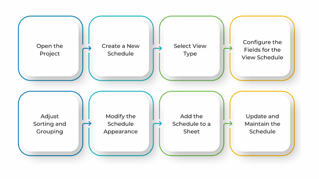
- Open the Project
Make sure your project is open in Revit. You should already have views created in your project before generating a schedule of those views.
- Create a New Schedule
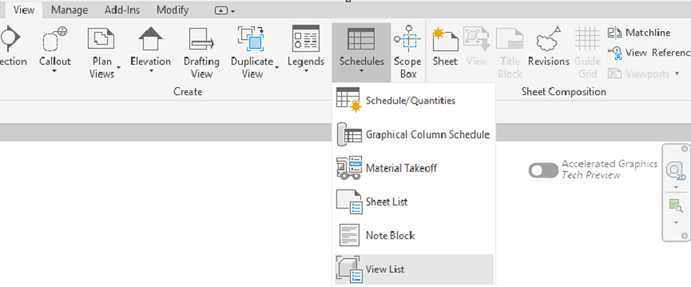
Go to the View tab on the ribbon. In the Create panel, click on Schedules, then select Schedule/Quantities.
- Select View Type
In the New Schedule dialog box, a list of categories will appear. Scroll down and select Views (found under the “Other” section), then click OK to proceed.
- Configure the Fields for the View Schedule
In the Schedule Properties dialog box, choose the fields you want to display in the schedule. Common fields include:
- View Name (e.g., Floor Plan, Section)
- View Type (e.g., Floor Plan, 3D View, Elevation)
- Discipline (Architecture, Structure, MEPF)
- Scale (view scale)
- Visibility/Graphics Overrides (view settings)
- Sheet (sheet number if the view is placed on a sheet)
Select the fields you need, then click OK to create the schedule.
- Adjust Sorting and Grouping
After creating the schedule, you can organise the information to make it easier to read. Click on Sorting/Grouping in the Properties palette or Schedule Properties dialog box. You can group views by View Type, Discipline, or Sheet and sort them by View Name or any other relevant field.
- Modify the Schedule Appearance
To improve readability, you can adjust formatting settings. In the Schedule Properties dialog box, go to the Formatting tab to hide blank values or adjust text size. In the Appearance tab, you can change the font size, alignment, and colours to customise the look of the schedule.
- Add the Schedule to a Sheet
To include the schedule in your documentation, open the sheet where you want to place it. Then, drag the newly created Schedule of Views from the Project Browser onto the sheet.
- Update and Maintain the Schedule
The schedule will automatically update when views are added, removed, or modified in the project. If you need to make changes (such as adding fields or adjusting sorting), right-click on the schedule in the Project Browser and choose Properties to update its settings.
Following these steps enables you to create efficiently create, organise, and manage a schedule of views in Revit, ensuring better project documentation.
BIM Supports GREEN EARTH.
Conclusion
Creating and managing views in Revit is key to organising your design and presenting it clearly. Whether you’re using drafting views, detail views, section views, or perspective views, knowing when and how to use them helps keep your workflow smooth and efficient.
Setting up your model properly, adjusting view properties, and organising views in schedules make it easier to coordinate your project. By following these steps, you can create clear, professional drawings that improve both design visualisation and construction planning.
Are you looking for BIM solutions?
BIM ASSOCIATES is your one-stop BIM Solution provider for the Architecture and Structure discipline. Their solutions help clients with better decision-making, cost-saving, efficient construction planning, and green earth initiatives.
You might also like: A Complete Guide to Adding, Customising, and Organising Revit Families.
FAQs (Frequently Asked Questions)
1. How can you have more than one view in Revit?
In Revit, you can create multiple views like floor plans, elevations, sections, 3D views, and schedules. You can also duplicate views to customise visibility settings. Any changes made in one view update automatically across all views, ensuring consistency.
2. How do you add views in Revit?
To add new views, go to the View tab on the ribbon. You can generate floor plans, sections, elevations, and other view types from there. Section views can be added from any view except a 3D view.
3. How do I add a starting view in Revit?
To set a starting view, open your model and go to the Manage tab. Under the Manage Project panel, click Starting View. In the Starting View dialog, choose the view you want as the default opening view, then click OK to save your selection.