Creating a toposurface in Revit helps you show the natural shape of the land in your project. It’s useful when designing buildings, roads, or landscapes that need to fit into real-world terrain. You can make the toposurface by using survey data, linking a DWG file with contour lines, or placing elevation points manually. Revit gives you easy tools to do all of this.
In this article, you’ll learn how to import elevation data, link DWG files to your project, and build a toposurface that matches the site. You will also learn how to change the surface later so the site works well with your design.
Importing Elevation Data
Importing elevation data is a key step in creating accurate site models and understanding terrain conditions. It helps integrate real-world topography into the BIM environment for better planning and design alignment.
Bringing elevation data into your GIS (Geographic Information System) or mapping software is essential to studying land height, creating topographic maps, planning for floods, and doing many other location-based tasks.
Usually, this means finding elevation data like Digital Elevation Models (DEMs) and getting them into a format your software can use. These models show the shape of the land using elevation values, which help you understand slopes, valleys, and high or low areas.
Depending on your project, you might use free data from government sources or purchase high-resolution datasets.
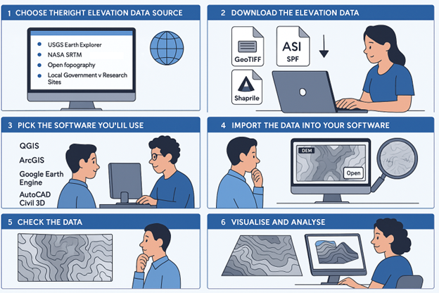
Below is a simple step-by-step guide to help you import elevation data correctly:
- Choose the Right Elevation Data Source
Before you start, pick a trusted source for your elevation data. Some popular options include:
- USGS Earth Explorer: Offers good-quality DEMs for the U.S. and some global areas.
- NASA SRTM: Gives worldwide elevation data, usually with 30 or 90-metre resolution.
- OpenTopography: Great for high-resolution elevation data, especially for specific regions.
- Local Government or Research Sites: Many countries share elevation data through official websites.
Ensure the data you pick suits your project’s location and level of detail.
- Download the Elevation Data
Once you find a suitable source, download the data. It usually comes in these formats:
- GeoTIFF (.tif): A raster file with both elevation and location info.
- ASCII (.asc): A simple text file with elevation numbers.
- Shapefile (.shp): Sometimes used for contour lines or 3D vector data.
Pick the correct area and resolution for your work. Also, check the metadata (file details) to ensure the data is recent and accurate.
- Pick the Software You’ll Use
Different software can import elevation data. Some common tools include:
- QGIS: Free and open-source, great for many types of GIS tasks.
- ArcGIS: A powerful tool used by professionals.
- Google Earth Engine: Good for cloud-based mapping and big data analysis.
- AutoCAD Civil 3D: Often used for engineering projects and terrain design.
Each one has its own way of loading elevation data, but they all support formats like GeoTIFF, ASCII, and shapefiles.
- Import the Data into Your Software
To import the data in different programmes, follow these steps for each of them:
QGIS
Open QGIS and go to Layer > Add Layer > Add Raster Layer. Find your downloaded DEM file and click “Open.” The data will appear on your map.
ArcGIS
Open ArcMap or ArcGIS Pro, click Add Data, and then select your DEM file. Click Add, and it will show on the map.
Google Earth Engine
Open the Earth Engine Code Editor and use this code to load DEM data:
javascript
Copy
Edit
var dem = ee.Image(‘USGS/SRTMGL1_003’);
Map.addLayer(dem);
AutoCAD Civil 3D
Open the programme and use the Import option to load your DEM or ASCII file. Follow the steps to turn it into a surface model.
- Check the Data
After importing, take a moment to make sure everything looks right. Is it in the correct spot on the map? Are the elevation numbers correct? You might need to reproject the data if it doesn’t line up with your map’s coordinate system.
- Visualise and Analyse
Now that the elevation data is ready, you can start using it:
- Draw Contour Lines: Turn elevation data into lines that show height changes.
- Build 3D Models: Create terrain that shows hills, valleys, and slopes.
- Run Water Studies: Use elevation data to analyse where water flows or floods.
After setting up your elevation data, the next step is to bring that information into your Revit project.
Also read: Optimising Floor Plan Views in Revit with View Range Settings
Linking DWG Files to Revit
Linking DWG files to Revit allows you to incorporate 2D CAD drawings into your BIM workflow without converting them into Revit elements. This helps maintain accuracy and coordination, especially when working with consultants or legacy project data.
Linking DWG files to Revit is a common and helpful method for architects, engineers, and construction teams. DWG files usually created in AutoCAD, often have essential details like site plans, mechanical layouts, or structural drawings needed in your Revit project.
Instead of redrawing everything from scratch, you can simply link the DWG file to Revit. This brings the design into your project while letting you update the DWG separately in AutoCAD. Revit treats the DWG as a reference, so any changes made in AutoCAD will automatically show up in Revit, helping you keep everything accurate and up to date.
Below is a step-by-step guide on how to link DWG files to Revit:
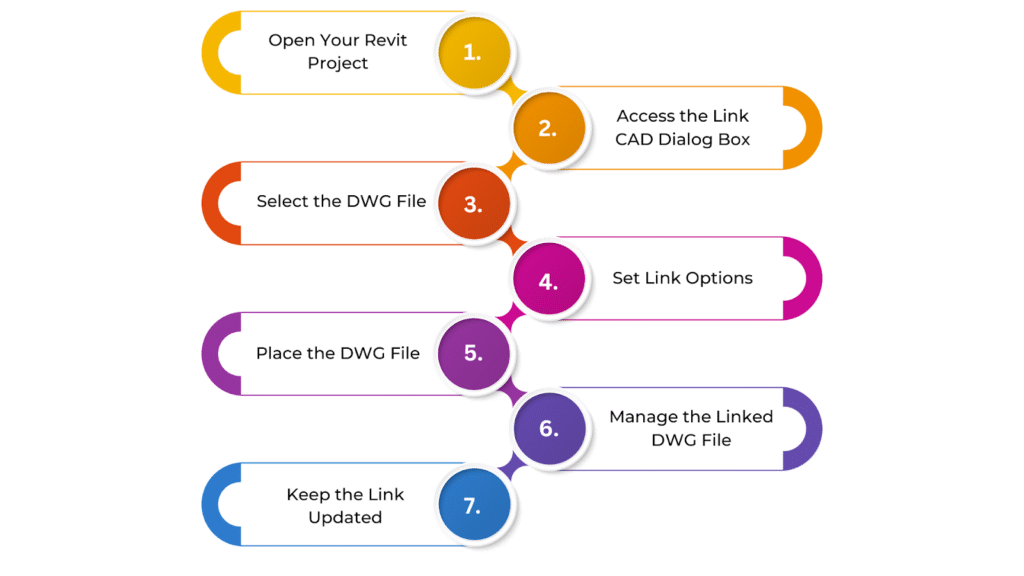
- Open Your Revit Project
Start by opening the Revit project where you want to add the DWG file. Before linking, it’s good to check that your project uses the correct units (feet or metres) and the right coordinate system. This helps ensure the DWG file lines up properly when brought into Revit.
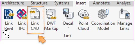
- Access the Link CAD Dialog Box
Once your project is open, go to the Insert tab at the top of the Revit screen. In the Link panel, click on Link CAD. This will open a new window called the Link CAD Formats dialog box. This is where you’ll choose the DWG file you want to link.
- Select the DWG File
In the dialog box that appears, click the Browse button. This lets you look through your folders to find the DWG file you want to use. Once you’ve located it, click on the file and hit Open to bring it into Revit.
- Set Link Options
Before the DWG file is linked, you’ll need to set a few options. First, choose how you want the DWG file placed in the Revit model. You can use Auto – Centre to Centre to put it in the middle, Auto – Origin to Origin to match the starting points of both files or Manual to click and place it where you want.
You can also pick how the colours appear—keep the original or switch them to black and white for better clarity. Then, decide which layers to bring in. You can choose all the layers from the DWG file or just the ones you need. Lastly, make sure the units of the DWG file match your Revit project. If they don’t, Revit will let you know so you can fix it.
- Place the DWG File
After setting all the options, click Open to place the DWG file into your Revit project. The file will now appear in your model, but you won’t be able to edit it directly. It will be a reference that you can move or align but not modify.
- Manage the Linked DWG File
If you need to move the DWG file or change where it sits in your model, just click on it and use Revit’s move or rotate tools. Go to the Manage tab and click Manage Links to manage the link. Here, you can reload the file, remove it, or change the link settings whenever you need.
- Keep the Link Updated
If the DWG file is changed or updated later in AutoCAD, you can bring those updates into Revit without re-linking the file. Go to Manage → Manage Links, find the linked DWG file in the list, and click Reload. This will refresh the link and bring in the latest version of the file.
Once your DWG file is successfully linked, you can use the imported contour lines or elevation points to build the toposurface.
Ready to simplify your projects and achieve the benefits?
BIM ASSOCIATES is your one-stop BIM Solution provider for Revit Architectural and Structural Solutions. They coordinate with your team to develop, record, and streamline the BIM Revit Model, along with the sheets, Bill of Quantities, Bill of Materials, and clash coordination.
Creating the Toposurface in Revit
Creating a toposurface in Revit helps you show the natural shape of the land in your project. The toposurface shows things like ground levels, slopes, and elevation changes, giving you a clear idea of how the land looks.
Revit has easy-to-use tools that let you build a 3D version of the land, which fits smoothly with your building model. This surface helps check the design, plan the groundwork, and make realistic views so your project matches the site it’s built on.
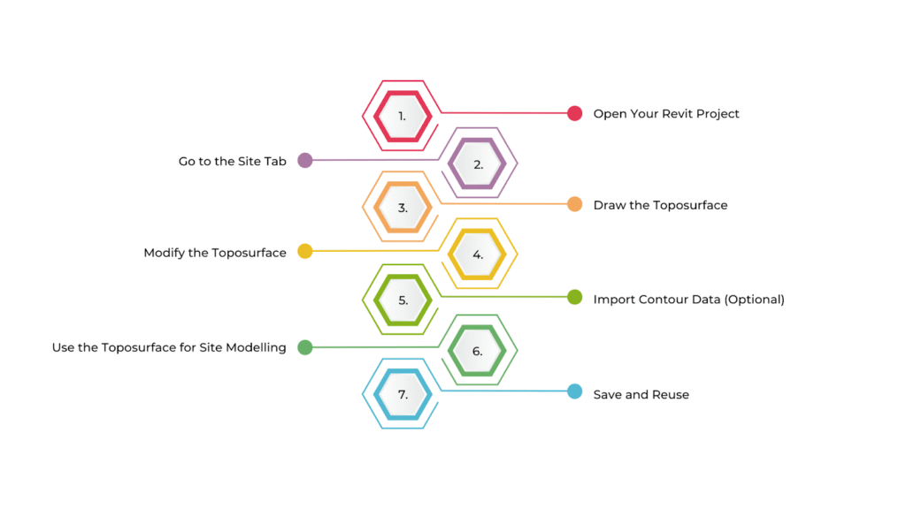
Below is a step-by-step guide to creating the Toposurface in Revit:
- Open Your Revit Project
Open the Revit project where you want to create a toposurface. Ensure you’re in a Site Plan or 3D View to see the terrain clearly. If there’s no site plan, create one by going to View > Plan Views > Site Plan.
- Go to the Site Tab
To access the topography tools, click on the Site tab in the Revit ribbon. In the Topography panel, click Toposurface to begin creating the surface.
- Draw the Toposurface
Click Place Point in the Draw panel, then click in the drawing area to start placing points. Revit will ask for an elevation value for each point—enter it manually or use the properties bar. Add more points to shape the terrain.
More points create a smoother, more accurate surface. Once done, right-click and select Finish Sketch to complete the surface.
- Modify the Toposurface
To make changes, select the toposurface and click Edit Surface. You can move or change existing points, delete them, or add new ones using Place Point. Use tools like Slope Arrow to adjust the slope or shape specific areas.
- Import Contour Data (Optional)
If you have contour lines in a CAD file, you can use them to generate the surface. Go to the Insert tab, click Link CAD, and choose your DWG file. Then, in the Site tab, select Create from Import to turn the contours into a toposurface. You can adjust elevations or add points if needed.
- Use the Toposurface for Site Modelling
Use the surface for tasks like grading or analysis. The Building Pad tool helps place buildings on uneven ground. You can check slopes and volume and cut/fill in the Analyse tab. For visualisations, apply materials and view the site in 3D for a more realistic presentation.
- Save and Reuse
Once finished, save your project. You can reuse the toposurface in other models or share it with your team for consistency across different files.
After you’ve created the initial toposurface, you may need to fine-tune it based on design updates or site requirements.
Modifying the Toposurface in Revit
Changing the toposurface in Revit is crucial when working on site design. It helps you match the terrain more closely to real-world conditions or adjust it to fit your building plan.
After creating the toposurface, you can easily edit it—add or remove points, change elevations, or reshape parts of the surface as needed. Revit gives you helpful tools to make these updates right inside your model so your site stays accurate and works well with the rest of your design.
Below is a step-by-step guide to modifying the toposurface in Revit:
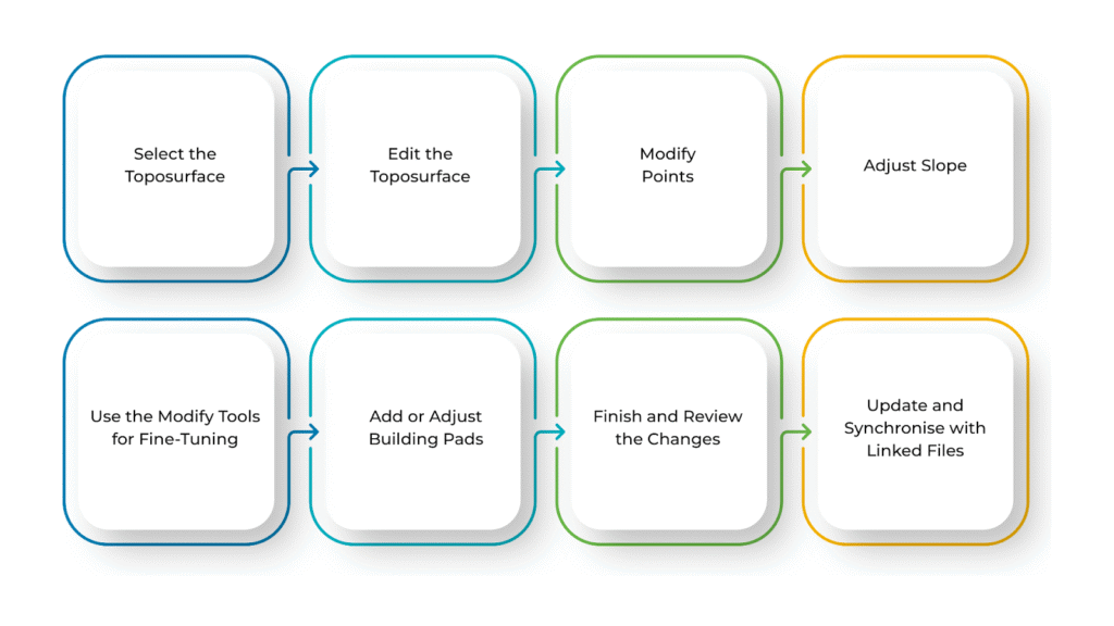
- Select the Toposurface
To start modifying the toposurface, you first need to select it for your project. Open a Site Plan or 3D View to see the terrain clearly.
Click on the toposurface in the drawing area. Once selected, it will be highlighted, and the Modify tab will appear at the top of your screen.
- Edit the Toposurface
Now that the toposurface is selected, go to the Modify tab and click on Edit Surface. This will let you make changes to the surface.
You’ll see several small points that make up the surface. These points control the shape and elevation of the terrain, and you can edit them as needed.
- Modify Points
You can change the shape of the toposurface by editing the points. To move a point, click on it and use the Move tool from the Modify tab. You can also type in a new elevation in the Properties bar.
If you want to remove a point, simply select it and press Delete—but be careful, as this might affect the shape of the surface. To add a new point, click on Place Point in the Modify tab, click on the drawing area, and then enter the elevation you want.
- Adjust Slope
You can adjust the elevation of multiple points to change how steep the terrain is. Select the points that form a slope and change their height using the Properties bar.
Use the Slope Arrow tool from the Site tab to precisely control the slope direction. Place the arrow to show where the slope should go and set the start and end elevations.
- Use the Modify Tools for Fine-Tuning
Revit offers more tools to refine your terrain. If you have two separate toposurfaces that need to become one, use the Join Geometry tool. Select the slope arrow and press Delete to remove a slope or adjust the surrounding points manually.
If you need to create different terrain areas with unique materials or heights, use the Split Surface tool to divide the toposurface into parts.
- Add or Adjust Building Pads
If you’re designing a building that sits on the terrain, use a Building Pad. Go to the Site tab and click on Building Pad, then draw the pad shape where your building will go.
Revit will automatically cut or raise the terrain under the pad. You can always go back and adjust the pad’s shape or position, and the surface will update to match.
- Finish and Review the Changes
Once you’ve finished making all the changes, click Finish Sketch to exit Edit Surface mode. Your toposurface will now show the updated shape. Use the 3D View to rotate and check if everything looks correct.
Also, review the Site Plan to ensure the surface lines up with your design. If contour lines are turned on, check that they reflect the new elevations.
- Update and Synchronise with Linked Files
If your project includes linked files like survey data or DWG files, keeping everything updated is essential. Go to the Manage tab and click on Manage Links.
Select the linked file and click Reload to bring in the latest version. This helps ensure your toposurface stays in sync with any external changes.
BIM Supports GREEN EARTH.
Conclusion
Once your toposurface is ready in Revit, it’s a good idea to do a final check to ensure everything looks right and works well. Look over the terrain to see if it matches the real site and fits your project’s needs. Also, check if any linked DWG files are still needed—if not, you can remove them to keep your project clean and organised.
As your design changes, the site data might change, too. So, keep an eye on any updates to the linked files and make changes to the toposurface if needed. This way, your model will stay accurate and up-to-date throughout the project.
Are you looking for BIM solutions?
BIM ASSOCIATES is your one-stop BIM Solution provider for the Architecture and Structure discipline. Their solutions help clients with better decision-making, cost-saving, efficient construction planning, and green earth initiatives.
You might also like: Autodesk Revit Viewer: Features, Access, and How to View Your Files.
FAQs (Frequently Asked Questions)
1. How to create mounds in Revit?
To create mounds in Revit, edit the toposurface and add points at a higher elevation where you want the mound. The more points you add around the centre, the smoother the mound will appear. Finish the sketch to apply the changes.
2. What is the difference between Toposolid and Toposurface in Revit?
Toposurfaces are older Revit elements used to model terrain with points and contours. Toposolids, introduced later, offer more control and can interact better with other elements like building pads and floors. They are more flexible for detailed site work.
3. Why does my Revit not have Toposurface?
If you can’t find the toposurface tool, ensure you’re in the proper Revit workspace. It’s usually under the “Massing & Site” tab. If it’s missing, check your Revit version—some newer versions replaced it with “Toposolid” under a different tab.