Fabrication drawings are crucial in the construction process. They provide clear visual details needed to turn designs into real building elements.. These drawings guide fabricators, engineers, and assembly teams, showing the specifications, dimensions, materials, and steps required to construct accurate and structural components.
From simple pieces to complex assemblies, they help ensure the process is smooth, precise, and error-free. In this article, you’ll explore the basics of fabrication drawings, their importance, types, and key components. You’ll also learn how they are created, the tools used, best practices for high-quality results, and how to solve common challenges in the drawing process.
What are Fabrication Drawings?

Fabrication drawings are detailed technical drawings used in construction to help built a specific component of the structure. They show exact measurements, materials, and assembly steps providing fabricators clarity on how to build the component correctly. These drawings include different views, notes, and specifications to avoid mistakes and ensure quality.
They are crucial for keeping production accurate and consistent. The construction industry depends on these drawings to ensure precise fabrication. Without them, miscommunication and mistakes can cause expensive rework and delays.
In order to understand its importance, it’s helpful to get an insight into its role and contribution to a project’s success.
Importance of Fabrication Drawings
Fabrication drawings play a crucial role in construction by ensuring that every structural and architectural component is built correctly. These detailed drawings guide fabricators, welders, and construction teams and help reduce mistakes and minimise the need for rework.
As a link between design and construction, these drawings ensure quality, efficiency, and compliance with industry standards. Fabrication drawings are essential for several reasons:
- Accuracy and Precision: Fabrication drawings provide clear, detailed instructions on how each component should be made. This ensures the final Structure aligns exactly with the design, reducing errors during production.
- Consistency: They help ensure that all parts are built the same way, whether for a large project or a series of similar building elements. This consistency is essential for quality control and ensuring components fit together properly.
- Better Communication: These drawings are a common language between engineers, designers, and fabricators. They help everyone involved understand the design and production details, preventing misunderstandings.
- Cost Savings: By giving precise measurements and specifications, fabrication drawings help reduce material waste and avoid expensive rework. This makes the production process more efficient and cost-effective.
- Compliance with Standards: Fabrication drawings often include details about materials, finishes, and tolerances to ensure they meet industry codes and safety regulations. This guarantees that the final component is compliant and safe to use.
- Assembly Guidance: Besides detailing individual parts, these drawings show how components should be assembled. This is especially important for complex structures, helping simplify the manufacturing and construction process.
- Documentation for the Future: Fabrication drawings serve as records of the completed work. They can be used for future repairs, replacements, or inspections, ensuring that important details are not lost over time.
Understanding the importance of fabrication drawings sets the stage for recognising the different types within this category. Each type fulfills a distinct purpose, catering to specific aspects of the fabrication process to ensure precision and clarity in production.
Also read: Understanding Architectural Drawings: Types, Techniques & Tips.
Types of Fabrication Drawings
Fabrication drawings come in different types, each designed for a specific purpose in construction. These detailed drawings help fabricators, welders, and construction teams assemble structural and architectural components accurately.
Knowing the different types of fabrication drawings helps make the construction process smoother, reduces mistakes, and ensures the project runs successfully. Below are the main types of fabrication drawings:
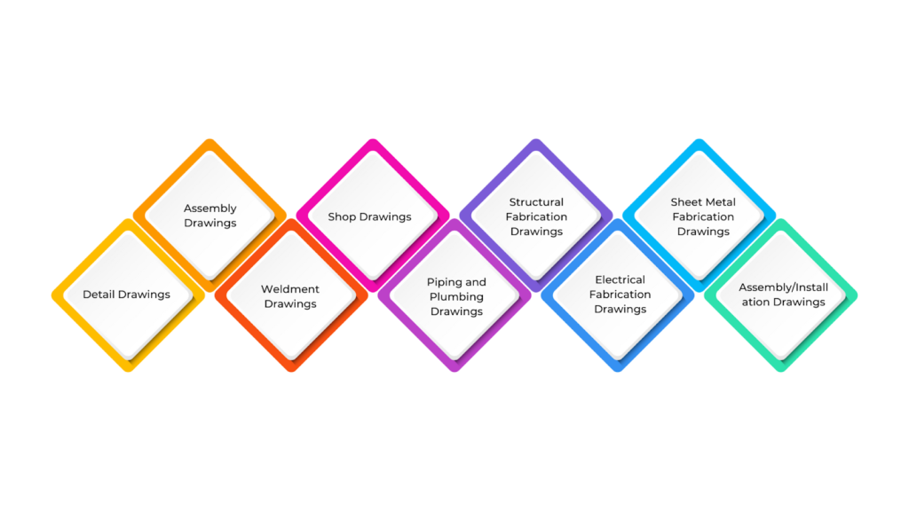
- Detail Drawings
These drawings provide a close-up view of a single part or component, showing its size, materials, and instructions for making it. They help fabricators create the part accurately.
- Assembly Drawings
These drawings show how different parts fit together to form a larger structure or product. They often include exploded views and part numbers to clarify how the components should be assembled.
- Weldment Drawings
Used for welding projects, these drawings show the parts to be welded, the type of weld to use, and the symbols for welding. They ensure that the joints are made correctly and securely.
- Shop Drawings
Manufacturers or fabricators use these drawings to guide the production process. They provide detailed measurements, material information, and sometimes instructions for assembling or making the parts.
- Piping and Plumbing Drawings
These detailed drawings are used to set up piping or plumbing systems. They show how pipes, valves, and other equipment should be laid out, along with their sizes and connections.
- Structural Fabrication Drawings
These drawings focus on building structural components like beams and columns. They include instructions for cutting, welding, and assembling the materials into the needed parts for construction projects.
- Electrical Fabrication Drawings
These drawings are for electrical systems and show where components like wiring, panels, and switches should go. They help installers set up the system correctly.
- Sheet Metal Fabrication Drawings
These drawings are used for making sheet metal parts and include details like cutting patterns, bends, and holes required to shape the metal into parts such as ducts or panels.
- Assembly/Installation Drawings
These drawings show how to assemble or install a structure on-site. They often include step-by-step instructions on the order of assembly and installation.
Each fabrication drawing plays a crucial role in ensuring the parts are made correctly, efficiently, and to the required standards, providing a clear guide for fabricators and assembly teams. To fully understand their role, it’s important to break down the various components that make up these detailed documents.
Ready to simplify your projects and achieve the benefits?
BIM ASSOCIATES is your one-stop BIM Solution provider for Revit Architectural and Structural Solutions. They coordinate with your team to develop, record, and streamline the BIM Revit Model, along with the sheets, Bill of Quantities, Bill of Materials, and clash coordination.
Components of Fabrication Drawings
When you’re working with fabrication drawings in construction, pay attention to all the details these documents include. They give the information needed to ensure everything is accurate and consistent during fabrication and assembly.
Each component is important in guiding the fabricator to create parts that meet the necessary specifications, ensuring accuracy, consistency, and high-quality results throughout fabrication.
Below are the key components of fabrication drawings:
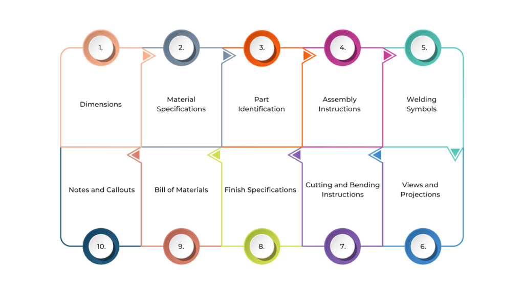
- Dimensions: These are the exact measurements of each part—length, width, height, and diameter. They ensure the parts fit together properly. Tolerances, or acceptable size variations, are also included here.
- Material Specifications: This tells you what materials should be used for each part, like steel, aluminium, or plastic. It also covers specific material grades, finishes, and other important manufacturing details.
- Part Identification: Each component gets a unique part number or label. This helps the team keep track of all the different pieces involved in the project.
- Assembly Instructions: If the fabrication involves multiple parts, these instructions explain how to assemble them. They might include detailed diagrams or references to assembly drawings.
- Welding Symbols: If welding is required, these symbols show the type, size, and location of the welds, as well as the welding technique to be used.
- Views and Projections: Different views of the part—such as top, side, and front projections—are included to fully understand its design. Sectional views can show internal features.
- Cutting and Bending Instructions: For parts made from materials like sheet metal, these instructions specify where cuts should be made and where bends should be formed.
- Finish Specifications: These specify the surface treatment required for the part, such as painting, coating, or leaving it raw. This ensures aesthetics and functionality, especially for parts exposed to wear or weather.
- Bill of Materials (BOM): This is a detailed list of all the materials and components needed for fabrication. It includes quantities, material types, and part numbers.
- Notes and Callouts: Any extra details, instructions, or clarifications that don’t fit the main categories are included here. These could be safety instructions, handling guidelines, or special considerations for the fabrication process.
Understanding the components of fabrication drawings is key to grasping their importance in the construction process. However, knowing what goes into these drawings is just one part of the equation. The process behind creating fabrication drawings ensures they meet the required standards and specifications for successful execution.
Creation of Fabrication Drawings
Creating fabrication drawings is an integral part of the construction process. These drawings turn design ideas into clear manufacturing and construction plans, and assembling parts. Architects, engineers, and fabricators work closely together to ensure every part is shown correctly and fits the project’s overall goals.
The drawings include detailed information like materials, measurements, and how parts should be assembled. Well-made fabrication drawings help reduce mistakes, speed up production, and ensure all the parts come together smoothly during construction.
Below is a step-by-step approach to creating fabrication drawings:
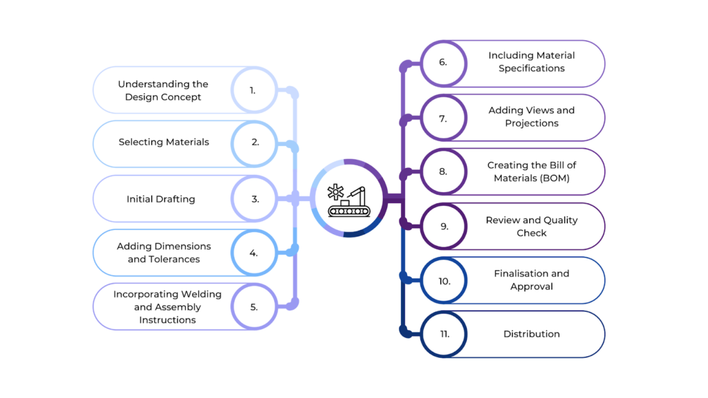
- Understanding the Design Concept
Before starting, it’s important to fully understand the design and the purpose of the component or structure. This might involve looking at architectural or engineering drawings for the overall idea.
- Selecting Materials
The materials for the component need to be chosen carefully. The drawing will include details about the type, grade, and finish of the material to ensure the component meets performance, durability, and aesthetic standards.
- Initial Drafting
The designer begins by using specialised BIM software (like AutoCAD or Revit) to create the first draft of the fabrication drawing. This step includes making 2D or 3D views of the component with accurate dimensions and shapes.
- Adding Dimensions and Tolerances
Exact measurements are added to the drawing to ensure the part is made correctly. Tolerances are also included, showing acceptable size variations to ensure the parts will fit together as planned.
- Incorporating Welding and Assembly Instructions
If welding is required, symbols are added to show where and how the welds should be made. If the part is part of a larger assembly, the drawing will include instructions on putting all the pieces together.
- Including Material Specifications
Details about the material, such as its grade, thickness, and finish, are added to ensure the right material is used for the job, providing strength and durability.
- Adding Views and Projections
Different views (top, side, front, sectional) are included to show the part from all angles. These views help fabricators understand the shape and structure of the part, even the complex details.
- Creating the Bill of Materials (BOM)
The BOM lists all materials, parts, and components needed for fabrication. It includes quantities, part numbers, and any other special notes for the parts.
- Review and Quality Check
Once the drawing is done, it’s reviewed for accuracy. The dimensions, materials, and all details are checked carefully, and any mistakes are fixed before finalising.
- Finalisation and Approval
After the review, the drawing is finalised and approved for production. This might involve getting input from other teams for cross-examination to ensure everything is in order.
- Distribution
The finalised drawings are sent to the teams that will use them to built the components. This could include fabrication shops or assembly lines where the parts will be made according to the drawings.
Creating fabrication drawings demands a careful blend of precision, expertise, and the right tools. With technology advancements, the software and tools used for these drawings have become more sophisticated, enhancing both efficiency and accuracy.
Software & Tools for Fabrication Drawings
Creating accurate and detailed fabrication drawings is key to a successful project in today’s construction industry. Architects, Engineers, designers, and fabricators use different software and tools to make this process easier.
These BIM (Building Information Modelling) tools help create precise drawings that meet project needs. They offer features that simplify tasks like adding dimensions, choosing materials, and planning how parts will be assembled, making the process more efficient and accurate.
Below are the top software and tools for fabrication drawings:
- AutoCAD: AutoCAD is among the most widely used software for making 2D and 3D fabrication drawings. It’s versatile and used in many industries, like construction, mechanical, and civil engineering.
- Revit: Revit is mainly used for Building Information Modelling (BIM), but it can also create fabrication drawings for building systems like HVAC, plumbing, and electrical installations.
- Tekla Structures: Tekla Structures is a BIM software for structural engineering and steel fabrication. It’s widely used in the construction and steel fabrication industries.
- SketchUp: SketchUp is an easy-to-use 3D modelling software ideal for quick design work. It’s popular in architecture, interior design, and basic fabrication.
- Fusion 360: Fusion 360 is a cloud-based CAD tool that combines 3D modelling, simulation, and collaboration features. It’s great for small to medium-sized businesses and freelancers.
- PlanGrid: PlanGrid is a cloud-based platform for construction management that helps teams access, share, and update project plans, including fabrication drawings.
While the right software and tools are fundamental in creating accurate fabrication drawings, the process doesn’t end there. Adhering to best practices ensures these drawings are precise and effective.
Best Practices for Creating Fabrication Drawings

Creating high-quality fabrication drawings while following best practices ensures accuracy, clarity, and consistency, helping the fabrication and assembly process run smoothly.
Sticking to established standards, working closely with fabricators, and using the right tools are all important steps in ensuring the drawings meet project needs and support an efficient construction process. Below are the best practices for creating fabrication drawings:
Understand the Design and Requirements
Before starting any drawing, it’s essential to clearly understand the design, how it should function, and what materials are needed. This step helps prevent mistakes and the need for rework during the fabrication process.
It’s also essential to communicate with other team members like engineers, designers, and fabricators to clarify any questions or uncertainties about the design.
Use Standardised Symbols and Notations
Using industry-standard symbols and notations, such as those for welding, material types, and dimensions, ensures that everyone can easily understand the drawing.
It’s also essential to ensure the drawing follows local and international standards like ASME, ISO, or AWS, including material specifications, welding guidelines, and tolerances. This helps avoid confusion and ensures the design meets industry requirements.
Provide Accurate Dimensions
Accurate and clear dimensions are crucial to avoid fabrication errors. Ensure that all key measurements are adequately noted and referenced. Also, tolerance values should be included to define acceptable variations in dimensions, guiding fabricators on what can and can’t be altered during manufacturing.
Incorporate Material Specifications
Clearly defining the material type, grade, and thickness, along with other characteristics, ensures the right materials are used in fabrication. This helps prevent defects or failures. Specifying the desired surface finish for the materials is also essential, as it impacts the product’s durability, aesthetics, and functionality.
Include Detailed Welding and Assembly Instructions
When welding is part of the process, standard welding symbols will show the type, size, and location of the required welds. This ensures fabricators understand the strength and type of weld needed.
For projects with multiple parts, provide assembly details, such as exploded views or clear instructions, to make it easier for fabricators to understand how components fit together.
Use Multiple Views and Projections
Include different views of the part, such as front, top, and side, to show the full geometry of the component. In addition, section views (cut-through views) can further explain the internal details. Exploded views are also beneficial when multiple parts must be assembled, showing how each part fits with the others.
Maintain Clarity and Simplicity
All text, numbers, and dimensions must be legible to avoid confusion. Using standard fonts and line weights makes the drawing easier to read. Additionally, avoid cluttering the drawing with unnecessary details—only include information directly relevant to the fabrication process.
Use a Bill of Materials (BOM)
A Bill of Materials (BOM) is essential to fabrication drawings. It lists all the materials, parts, and components required for the project, helping fabricators quickly find what they need. Assigning part numbers to components also simplifies the identification and ordering process, keeping things organised.
Review and Verify Drawings
Once the drawing is complete, reviewing it for accuracy is important. Double-check all dimensions, material specifications, and other critical details to ensure they’re correct. Having a peer or supervisor review the drawing before finalising it helps catch any errors or inconsistencies.
Provide Clear Notes and Callouts
In addition to the drawings, use callouts and notes to clarify any ambiguities or special instructions that may not be easy to convey just through the visuals. Adding these notes can highlight specific requirements, like finishing details, tolerance limits, or other special considerations that must be followed during fabrication.
Ensure Proper File Management
Maintaining proper file management is crucial for keeping track of different versions of the drawing. Version control ensures that everyone utilises the latest updated drawing version. It’s also important to store backups of the drawings, including older versions, in case they’re needed for future reference or modifications.
Consider the Fabrication Process
When creating the drawings, always keep the limitations of the manufacturing process in mind. The design should be feasible to produce, avoiding overly complex or challenging features that may be hard to fabricate.
Engaging with fabricators early in the process allows them to provide feedback on the design and helps identify any potential challenges before the fabrication starts.
Use BIM Software Effectively
BIM software like AutoCAD or Revit can help in creating more efficient and accurate fabrication drawings. These tools allow for precise dimensioning and 3D modelling, which helps visualise the design before it’s built.
BIM features like automatic dimensioning, part libraries, and clash detection can save time and improve the accuracy of the drawings.
Following these best practices when creating fabrication drawings ensures the resulting designs are accurate, clear, and easy to follow. However, even when you’re following best practices, creating fabrication drawings can present unique challenges.
Challenges & Solutions in Fabrication Drawings
Fabrication drawings are crucial in construction, but creating them can be challenging. These challenges include dealing with complex designs, coordinating with multiple teams, ensuring accuracy, and managing tight deadlines. Each of these factors affects the quality and usefulness of the drawings.
By understanding these challenges and applying practical solutions, construction teams can overcome these obstacles. Below are the key challenges and solutions in fabrication drawings:
| Challenges | Solutions |
| Inaccurate Dimensions | Use precise measurement tools and double-check all dimensions before finalising the drawing.Implement a review process to catch errors early. |
| Lack of Standardisation | Adhere to industry-standard symbols, notations, and practices (e.g., ASME, ISO, AWS) to maintain consistency across drawings. |
| Complexity in Design | Break down complex designs into manageable sub-assemblies, use exploded views, and create detailed assembly instructions. |
| Unclear Material Specifications | Include exact material types, grades, and finishes in the drawing.Use a Bill of Materials (BOM) to list materials clearly. |
| Inconsistent Welding Symbols | Use standard welding symbols and ensure the correct placement and type of welds.Provide detailed notes for specialised welding techniques. |
| Ambiguity in Assembly Instructions | Provide exploded views and step-by-step assembly instructions, referencing other related drawings for clarity. |
| Overcrowded Drawings | Simplify the drawing by removing unnecessary details.Focus on the critical dimensions, specifications, and key instructions. |
| Difficulty in Collaboration | Use cloud-based BIM tools for real-time collaboration and version control, ensuring all stakeholders have access to the latest version. |
| Software Compatibility Issues | Choose widely-used BIM software like AutoCAD or Revit, which can export to multiple formats, ensuring compatibility across teams. |
| Changes in Design During Fabrication | Establish a clear change management process to ensure any modifications are accurately reflected in the drawings and communicated to the team. |
| Difficulty in Understanding Drawings | Keep text legible and dimensions clear, and avoid over-complicating the presentation.Utilise annotations and legends to explain complex parts. |
| Errors in Tolerances | Clearly define tolerances for critical dimensions and verify them through simulations or calculations to ensure they are achievable during fabrication. |
By recognising these challenges and applying the appropriate solutions, fabrication drawings can be created with greater accuracy and efficiency, ultimately improving the overall manufacturing process.
BIM Supports GREEN EARTH.

Conclusion
Fabrication drawings are vital for turning designs into real parts and structures. They provide clear and detailed instructions, helping reduce errors, improve efficiency, and ensure high-quality results.
Using the right tools, following industry standards, and sticking to best practices helps teams work more smoothly and get better outcomes. As the need for accuracy and efficiency grows, fabrication drawings play an even more important role. Properly created drawings also ensure that all team members stay aligned, avoiding costly mistakes and delays.
Are you looking for BIM solutions?
BIM ASSOCIATES is your one-stop BIM Solution provider for the Architecture and Structure discipline. Their solutions help clients with better decision-making, cost-saving, efficient construction planning, and green earth initiatives.
You might also like: Section Drawings in Architecture: Key Elements, Types, & Best Practices.
FAQs (Frequently Asked Questions)
1. How do you identify fabrication drawings?
Fabrication drawings are detailed illustrations used to guide the construction or manufacturing of components. They typically include precise measurements, material specifications, and assembly instructions. These drawings highlight every element required to produce the part, including welding or joining details.
2. What is the difference between shop drawing and fabrication drawing?
Shop drawings focus on how a contractor or fabricator will construct a component, often showing installation details. Fabrication drawings, however, are more detailed, focusing on how to actually build and assemble parts, specifying materials, dimensions, and techniques like welding.
3. How do you read drawings for fabrication?
To read fabrication drawings, first focus on the dimensions, material specifications, and assembly instructions. Understand the symbols used for welds, cuts, and finishes, and look for part numbers and views from different angles. Pay attention to detailed views that provide close-up information on complex areas to ensure correct fabrication and assembly.