Isometric drawing is useful for showing 3D objects on a flat surface. It helps architects, engineers, and designers create clear and accurate visuals of buildings and structures. Unlike perspective drawings, isometric drawings keep all dimensions true to scale without shrinking or distorting as they move further back. This makes them great for showing precise measurements and spatial relationships.
In this article, you’ll explore why isometric drawing is important in architecture, its benefits, different types of isometric diagrams, and the key principles and best practices for creating them effectively.
What is Isometric Drawing?
An isometric drawing is a way to show a 3D object on a flat surface while keeping its shape and proportions. In this type of drawing, the height, width, and depth are drawn at equal angles, usually 120 degrees apart. This gives the drawing a three-dimensional look and adds depth.
Isometric drawings make it easier to see multiple sides of an object at the same time, helping viewers or reviewers understand its shape and details. They are widely used in engineering and technical drawings because they provide accurate measurements and a clear view of complex designs.
While isometric drawings offer a clear and accurate way to visualise an object from multiple angles, they differ from perspective drawings in how they represent depth and proportion.
Difference Between Isometric Drawing and Perspective Drawing
In design, two common ways to show 3D objects on a flat surface are isometric drawing and perspective drawing. Both aim to represent three-dimensional shapes, but they do it differently, which results in unique looks. Isometric drawings show objects in a uniform way, where all angles and sizes stay the same.
On the other hand, perspective drawings give a more realistic view, mimicking how we see the world, with lines that meet at points in the distance. Knowing the difference between these two methods is important for designers, architects, and illustrators since each one works best for different purposes.
Below are the differences between isometric drawings and perspective drawings:
| Feature | Isometric Drawing | Perspective Drawing |
| Definition | A method of showing 3D objects with equal scaling along all axes. | A technique that creates a realistic 3D view, with lines converging to vanishing points. |
| Angles | All angles are equal, usually 30° from the horizontal. | Angles change as objects recede into the distance. |
| Proportions | Proportions remain consistent throughout the drawing. | Proportions change based on the object’s distance from the viewer. |
| Realism | Looks more like a technical diagram, less realistic. | More realistic, mimicking how we perceive depth in the real world. |
| Common Use | Often used in technical drawings, engineering, and game design. | Used in art, architecture, and design for realistic visuals. |
| Visual Effect | Objects appear uniform in size, regardless of depth. | Objects get smaller as they move further away, creating depth. |
| Lines | All lines are parallel and do not meet. | Lines converge towards vanishing points. |
Understanding the differences between isometric and perspective drawings helps in choosing the right technique for architectural visualisation. While both methods depict three-dimensional objects, they serve different purposes. However, isometric drawing is particularly beneficial in architecture.
Benefits of Isometric Drawing in Architecture
Isometric drawings are useful in architecture because they show buildings and structures in a clear 3D view. Unlike flat 2D blueprints, these drawings let architects, engineers, and clients see the design from different angles without any distortion.
This helps everyone understand the layout better, improves communication, and makes planning and construction more accurate. Whether used for design ideas, technical documents, or presentations, isometric drawings make projects easier to visualise and more efficient to develop.
Below are the benefits of isometric drawings in architecture:
- Clear Visualisation: Shows a building or object in 3D, making it easy to see its height, width, and depth all at once.
- Accurate Representation: Keeps the true proportions, helping to understand how different parts fit together.
- Easy Measurement: Allows direct measurement from the drawing, simplifying planning and construction.
- Better Communication: Helps architects, builders, and clients understand designs without needing multiple views.
- Efficient Space Planning: Helps organise layouts effectively, ensuring smart use of space.
- No Distortion: Unlike perspective drawings, it keeps dimensions and angles accurate for precise design and construction.
Beyond their benefits, isometric drawings come in different types, each serving a specific purpose in architectural design.
Also read: Detailed Drawings in Architectural Design: Types & Creation Process.
Types of Isometric Architectural Diagrams
Isometric architectural diagrams come in different types, each helping to visualise and explain design ideas in a clear 3D view. They turn complex spatial details into easy-to-understand drawings and make it simpler for architects, engineers, and clients to grasp a project.
Some diagrams, like exploded isometric views, break down a structure into parts, while others, like layered views, focus on different building systems. Knowing these diagram types helps architects communicate ideas better, analyse details, and improve project planning.
Below are the types of isometric architectural diagrams:
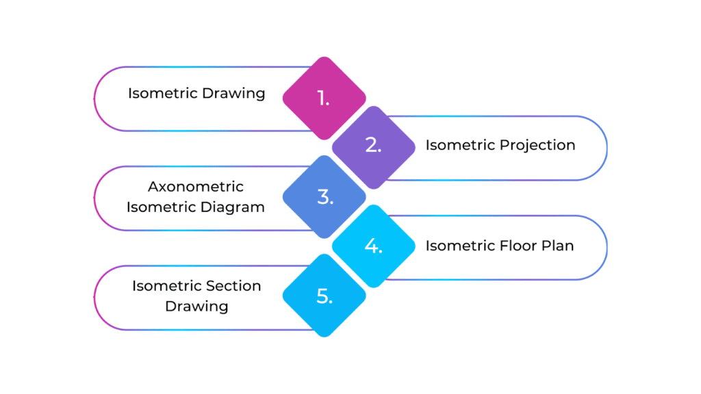
Isometric Drawing (Full Isometric)
An isometric drawing shows a building or structure in 3D, making the height, width, and depth clearly visible. It keeps the proportions accurate and represents the entire design in a realistic way. These drawings are commonly used for concept designs and technical presentations.
Isometric Projection
This is a precise technical drawing that follows strict isometric rules. It maintains equal scaling in all directions and keeps a 120-degree angle between the axes. These drawings are mainly used in construction documents to ensure accuracy in measurements and structural details.
Axonometric Isometric Diagram
This type of isometric drawing helps show how spaces and volumes relate to each other in a building. It gives a clear 3D view without distortion and can highlight specific areas like floor plans, facades, or interiors to show how space is used.
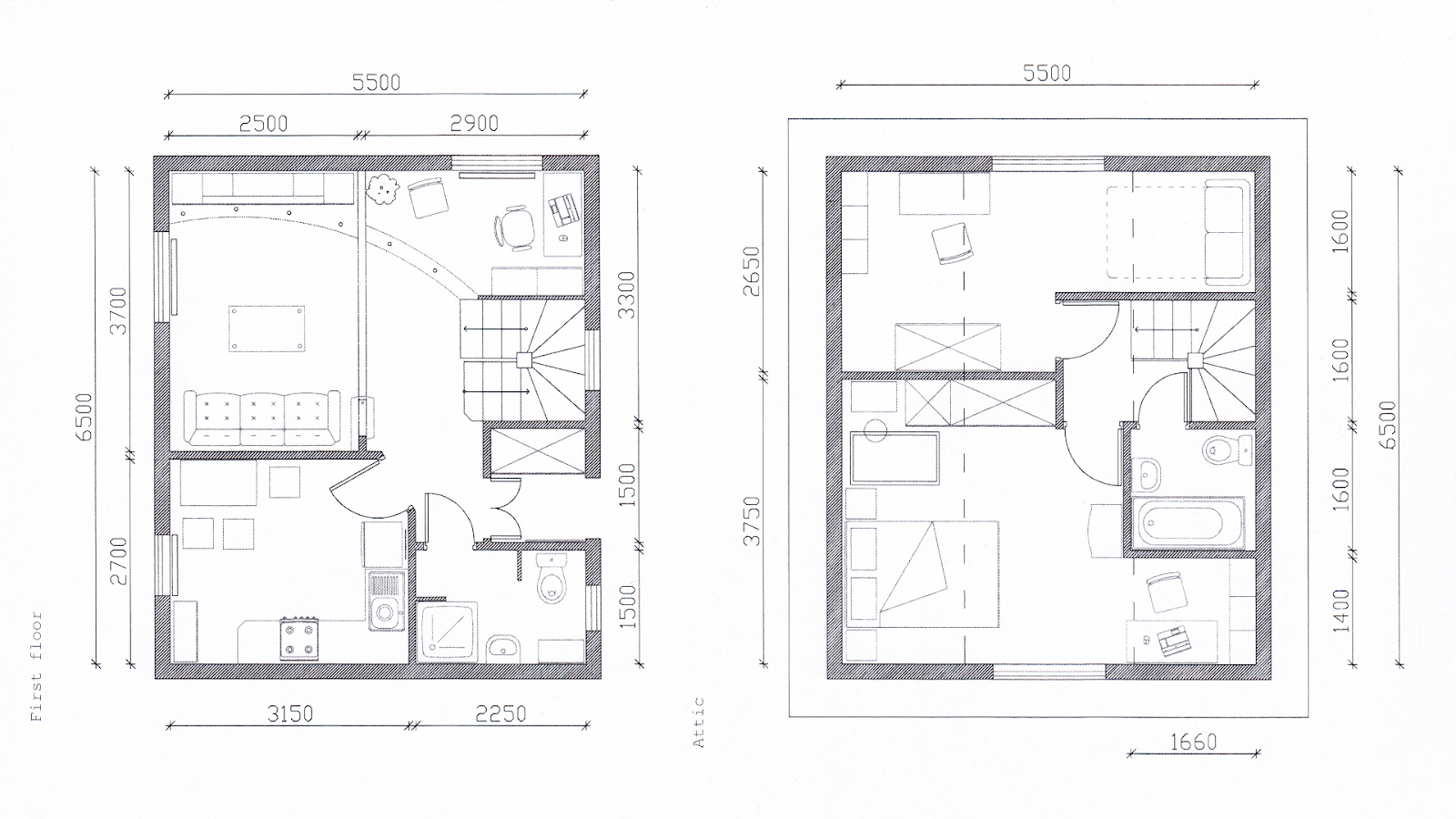
Isometric Floor Plan
An isometric floor plan is a 3D layout of a building’s floor, showing how rooms and other spaces connect. It helps understand how different parts of a building interact regarding width, height, and depth.
Isometric Section Drawing
This drawing provides a cross-sectional view of a building, showing how different levels and structural components fit together. It helps visualise the relationship between floors and elements like walls, staircases, and doors.
By using isometric drawings, architects can explore different aspects of a building’s design in a clear and detailed way. These drawings come in various forms, each serving a specific purpose in architectural planning and communication.
Ready to simplify your projects and achieve the benefits?
BIM ASSOCIATES is your one-stop BIM Solution provider for Revit Architectural and Structural Solutions. They coordinate with your team to develop, record, and streamline the BIM Revit Model, along with the sheets, Bill of Quantities, Bill of Materials, and clash coordination.
Examples of Isometric Drawings in Architecture
Isometric drawings are widely used in architecture to present designs, structures, and spaces in a clear and simple way. These 3D drawings help architects, engineers, and clients understand complex designs with accuracy and detail.
There are different types of isometric drawings, each serving a unique purpose. They improve visualisation, make documentation easier, and enhance collaboration during the design and construction process. Here are some common examples of isometric drawings used in architecture:
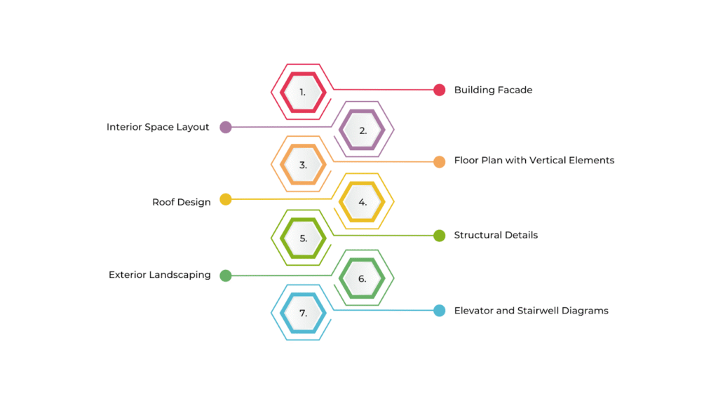
Building Facade
An isometric drawing of a building’s facade shows the front, side, and top views at the same time. This helps architects display the building’s proportions, windows, doors, and design details in one clear image without the distortion seen in perspective drawings.
Interior Space Layout
Isometric drawings of interiors show how rooms, furniture, and fixtures are arranged within a building. They provide a realistic 3D view of the space and make it easy to understand how everything will look when completed, including walls, floors, ceilings, and furniture placement.
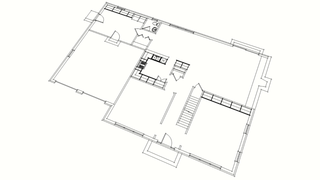
Floor Plan with Vertical Elements
A combined isometric floor plan includes both the horizontal layout (such as rooms and hallways) and vertical elements (like walls and windows) in one drawing. This makes it easier to see how different floors connect and fit into the overall structure.
Roof Design
Architects use isometric drawings to illustrate roof designs, including slopes, materials, and architectural features like chimneys or skylights. These drawings also show how the roof connects to the rest of the building.
Structural Details
Isometric drawings help highlight specific architectural features such as staircases, elevators, and columns. These drawings clearly understand how these elements fit within the design, including their dimensions and placement.
Exterior Landscaping
Isometric drawings also show outdoor elements like gardens, patios, and pathways. They help visualise how landscaping integrates with the building and surrounding environment, giving a realistic 3D view of the outdoor space.
Elevator and Stairwell Diagrams
Isometric views help show vertical transportation systems in multi-storey buildings, such as elevators and stairwells. These diagrams make it easier to understand how floors connect and where elevators or staircases are positioned within the structure.
These examples show how isometric drawings help in architecture by giving a clear and practical view of both the inside and outside of a building. Seeing isometric drawings in real-world architecture helps illustrate their usefulness, but understanding their principles is also essential.
Principles of Isometric Drawing
Isometric drawing uses simple rules to create clear and accurate 3D images of architectural designs. Unlike perspective drawings, isometric drawings keep everything at the same size. This makes it easier to see the design clearly and understand the proportions.
By following these basic principles, architects and designers can create detailed and easy-to-read illustrations. The principles of isometric drawings include:
- Equal Angles: The height, width, and depth are drawn at 120-degree angles, creating a balanced 3D view.
- Parallel Lines: Lines that are parallel in the real object stay parallel in the drawing, keeping proportions accurate.
- Equal Scaling: All three directions (X, Y, and Z) are scaled the same way, so the object’s size remains true.
- No Perspective Distortion: Objects don’t shrink or change shape as they move further away, unlike in perspective drawings.
- Vertical Lines Stay Straight: Any vertical lines in the object remain perfectly straight in the drawing.
- Follows Isometric Grid: Horizontal lines align with the isometric grid, ensuring correct proportions.
- No Foreshortening: Objects are shown at full scale in all directions, even when extending into depth.
These principles allow for clear, accurate, and easily readable representations of objects, particularly in fields like architecture. However, applying these principles in practice requires specific techniques and steps to bring designs to life.
Creating Isometric Drawing in Architecture
Creating an isometric architectural drawing follows a clear process to accurately show 3D objects on a flat surface. Architects and designers use these drawings to clearly represent building layouts, interior spaces, and construction details.
Creating an isometric drawing in architecture involves a series of steps to ensure an accurate representation of a structure or design. Below is a step-by-step approach to create an isometric drawing:
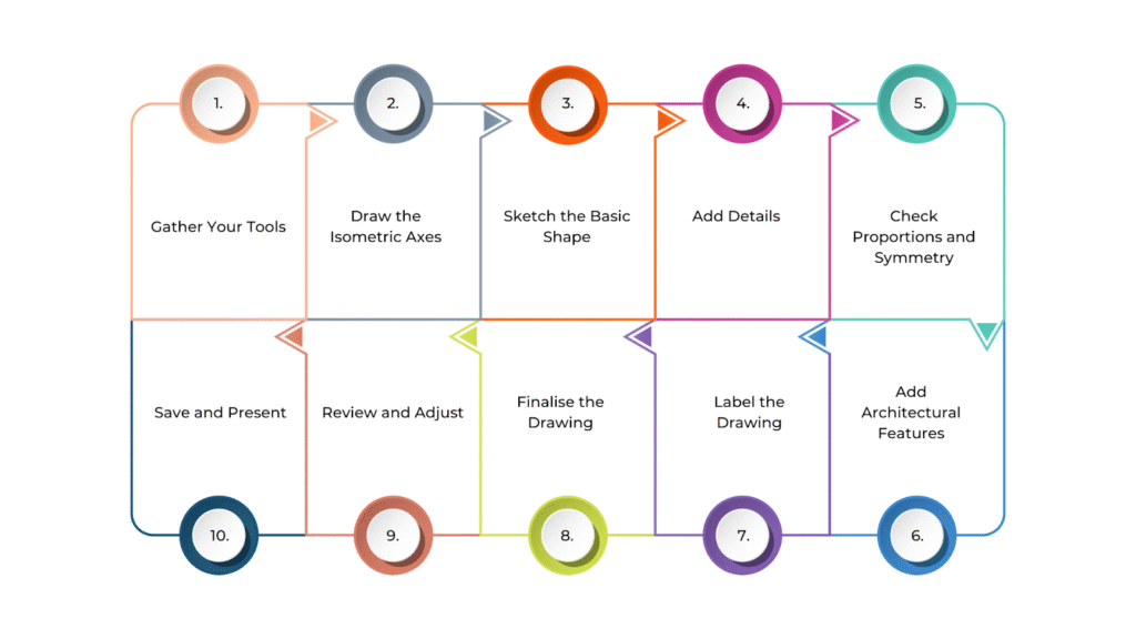
- Gather Your Tools
If drawing by hand, use graph paper, a protractor, a ruler, a pencil, an eraser, and a fine liner or pen for final details. If working digitally, CAD software will help maintain accuracy. An isometric grid can also guide angles and proportions.
- Draw the Isometric Axes
Start by sketching three main axes at 120-degree angles from each other. These represent height (vertical), width (forward-left), and depth (backward-right). Keeping these angles correct ensures an accurate isometric view.
- Sketch the Basic Shape
Use the isometric axes as a guide to draw the main structure. For example, if you’re sketching a rectangular room, create the front face as a parallelogram.Make sure the length, width, and height are in the right proportions.
- Add Details
Draw walls, windows, and doors, ensuring vertical lines stay straight, and horizontal lines follow the isometric grid. For stairs and fixtures, keep all lines parallel where necessary. If a sloped roof is included, adjust the angles carefully while following the 120-degree rule.
- Check Proportions and Symmetry
Make sure all parts of the drawing are consistent and scaled. Since isometric drawings represent real-world objects, each axis should maintain the same proportional measurements.
- Add Architectural Features
Include textures, furniture, flooring, or landscaping to give the drawing more depth and realism. While isometric drawings don’t show perspective, shading can help make different surfaces stand out.
- Label the Drawing
Add dimensions to show the size of different parts of the structure. You can also include short notes explaining materials or special design features.
- Finalise the Drawing
If working by hand, go over the lines with a fine liner or pen to make them clear and sharp. Once the ink is dry, erase any extra guidelines or rough sketches.
- Review and Adjust
Check for any mistakes in scaling, angles, or proportions. If something looks off, make corrections to improve clarity and accuracy.
- Save and Present
If you’re using digital software, save the file in a suitable format like PDF, JPG, or CAD. If the drawing is hand-drawn, consider scanning or taking a high-quality photo for digital use or printing.
Creating an isometric drawing requires attention to detail, precision, and the right techniques to ensure clarity and accuracy. To achieve the best results, it’s essential to follow certain best practices that enhance the effectiveness of these drawings.
Best Practices While Creating Isometric Drawing
Creating a good isometric drawing in architecture requires careful attention to detail. All elements should maintain a consistent scale to ensure accuracy. Clean and precise lines help make the drawing clear and easy to understand. Adding labels, shading, or colour coding can further improve readability and highlight important design features.
Below is a list of best practices for creating isometric drawings
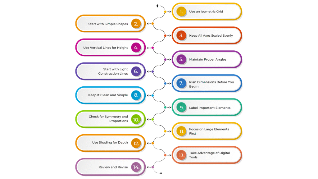
- Use an Isometric Grid: An isometric grid helps you keep all angles at 120 degrees, ensuring everything stays properly scaled and aligned. This prevents distortion and keeps the drawing accurate.
- Start with Simple Shapes: Begin with basic shapes like cubes or rectangular prisms. This makes it easier to build your design step by step, adding complexity as you go.
- Keep All Axes Scaled Evenly: In isometric drawing, height, width, and depth should be scaled equally. This keeps the proportions correct and prevents any part from looking stretched or shrunken.
- Use Vertical Lines for Height: Vertical lines should always remain straight up and down. This keeps walls, columns, and other vertical elements accurate and avoids skewed perspectives.
- Start with Light Construction Lines: Use light lines to sketch out the structure before finalising details. These can be adjusted or erased as needed, making it easier to refine your design.
- Plan Dimensions Before You Begin: Know the exact measurements of each part of your design in advance. This helps prevent mistakes and ensures accuracy in the final drawing.
- Keep It Clean and Simple: Avoid adding too many details that could clutter the drawing. Focus on essential features so the design remains clear and easy to read.
- Label Important Elements: Mark key parts like windows, doors, and dimensions. This makes it easier for others to understand the drawing at a glance.
- Check for Symmetry and Proportions: Make sure all parts of the drawing are balanced and correctly sized. Regularly compare with reference materials to maintain consistency.
- Focus on Large Elements First: Start with big components like walls and floors before adding smaller details. This makes it easier to adjust the layout if needed.
- Use Shading for Depth: Adding shading helps create a 3D effect, making different surfaces stand out. This improves readability, especially in complex designs.
- Take Advantage of Digital Tools: Software like CAD programs can help automate scaling and improve accuracy. Digital tools also make it easier to edit and refine your drawing.
- Review and Revise: Check your drawing regularly for errors. Make corrections at each stage to ensure the final version is precise and well-structured.
BIM Supports GREEN EARTH.
Conclusion
Isometric drawing helps architects and designers show 3D structures on a 2D surface while keeping the proportions and scale accurate. This makes it easier to communicate spatial layouts and construction details clearly. It also helps develop and improve design ideas, making the process more organised and efficient.
With isometric drawings, professionals can create detailed and easy-to-understand visuals that improve teamwork and decision-making. This technique is useful for both planning and presenting architectural projects.
Are you looking for BIM solutions?
BIM ASSOCIATES is your one-stop BIM Solution provider for the Architecture and Structure discipline. Their solutions help clients with better decision-making, cost-saving, efficient construction planning, and green earth initiatives.
You might also like: Section Drawings in Architecture: Key Elements, Types, & Best Practices.
FAQs (Frequently Asked Questions)
1. Is isometric drawing 2D or 3D?
An isometric drawing is a 2D representation of a 3D object. It uses parallel lines at 30-degree angles to create the illusion of depth without perspective distortion.
2. Who uses isometric drawings?
Engineers, architects, and designers use isometric drawings. They help visualise objects, structures, and products in a way that shows multiple sides clearly.
3. Why is shading used when drawing?
Shading adds depth, realism, and detail to a drawing. It helps show light, shadows, and textures, making objects look more three-dimensional and visually clear.