In 2025, over 12,452 companies around the world have adopted Autodesk Revit, recognising its powerful capabilities for building design and construction. One of the key tools that enhances Revit’s usability is the Properties Panel, which allows you to quickly access and modify the settings of selected elements.
Whether it’s adjusting dimensions, changing materials, or fine-tuning visibility, the Properties Panel makes these tasks quick and efficient. However, there are times when the panel may disappear, disrupting your workflow.
Knowing how to restore the Properties Panel is essential to maintaining a smooth design process and ensuring your work stays efficient and uninterrupted.
In this article, you will understand Plan View Properties, their categories, and why the Properties Panel might go missing. You’ll also learn how to restore it and disable Auto Apply for better control over your design process.
What are Plan View Properties in Revit?

In Revit, Plan View Properties control how a floor plan, ceiling plan, or structural plan looks and behaves. These settings let you adjust things like scale, visibility, detail level, and view templates.
For example, you can change the view range, which decides how much of the model you can see above or below a certain cutting plane. You can also modify visibility settings to show or hide specific elements, like turning off furniture or displaying only certain annotations.
These properties help ensure your plan view clearly shows the right part of the building model, making it easier for design and documentation. To make the most of Revit’s plan views, it’s essential to understand the different types of properties that control their appearance and behaviour.
Also read: Revit Tutorial: Elevation Views, Levels, and Spot Elevations Guide.
Different Categories of Plan View Properties in Revit
In Revit, Plan View Properties decide what is visible, how elements look, the depth of the view, the scale, and annotation details. By adjusting these properties correctly, users can keep their project documents clear, consistent, and accurate.
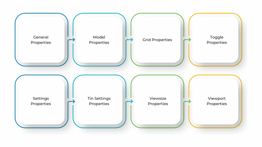
Plan View Properties are divided into different categories, each handling a specific aspect of the view. Below is a simple breakdown:
- General Properties
These settings define the basic details of the plan view:
- View Name: The title of the view.
- View Scale: Controls how zoomed in or out the view appears.
- View Range: Defines which parts of the model (above, below, and at the cut plane) are visible.
When you open the View Properties panel, you will see the General Information section. In the General area, you can change the View Name and Background Colour:
- To rename the view, click on the current name, type a new one, and press Enter to confirm.
- To change the background colour, select the Colour button and choose a colour from the dropdown list.
The View Data section shows details about the view’s extent, including the minimum and maximum X, Y, and Z values. It also displays the number of elements and vertices/points in the view. Once you’re done, click Finish to close the panel.
- Model Properties
These settings affect how model elements appear:
- Visibility/Graphics: Controls which elements (walls, floors, roofs, etc.) are visible.
- Detail Level: Adjusts the level of detail (Coarse, Medium, Fine).
To control which models appear in your view, follow these steps:
- Select ‘Models’ from the left-hand side (LHS) tree structure.
- On the right-hand side (RHS) panel, you’ll see:
- ‘Models on View’: A list of models currently visible in the view.
- Available Models: Models that are not in the view but can be added.
Between these two lists, there are four buttons to add or remove models:
| Buttons | Key Details |
| Top Button – Add All to View | Adds all available models to the view. |
| Second Button – Add to View | Adds only the selected model(s). You can select one or multiple models. |
| Third Button – Remove All from View | Removes all models from the view, leaving it empty. |
| Bottom Button – Remove from View | Removes only the selected model(s). |
On the RHS panel, there are five buttons to adjust the order in which models are drawn. The model at the top is drawn first, and the last one appears on top of all others. For example, if you have a raster image, placing it at the bottom is best so other model elements remain visible.
The sorting buttons include:
| Buttons | Key Details |
| Top Button – Sort Alphabetically | Arrange models in A-Z order. |
| Second Button – Move to Top | Moves selected model(s) to the top. |
| Third Button – Move Up | Moves selected model(s) one step higher in the list. |
| Fourth Button – Move Down | Moves selected model(s) one step lower in the list. |
| Bottom Button – Move to Bottom | Moves selected model(s) to the bottom. |
These options allow you to easily manage which models appear in your view and control their display order.
- Grid Properties
Grids help align elements in the model. These properties control how they display:
- Grid Visibility: Turns grid lines and labels on or off.
- Grid Display: Defines grid line styles (solid, dashed, etc.).
To control grid visibility and settings, follow these steps:
- Select ‘Grids’ from the left-hand side (LHS) tree structure.
- The grid properties will allow you to turn grids on or off in the view.
You can choose how grids appear in the view:
- No Grids: No grid lines will be visible.
- Draw Grids Last on View: Grids will be drawn last, meaning they will sit on top of models.
- Draw Grids First on View: Grids will be drawn first, meaning they will sit below models.
These settings control how the grid lines and text appear:
- Grid Mode: Defines how grids are displayed:
- Full Lines: Solid lines at set x (east) and y (north) spacing.
- Crosses: Small crosses at grid intersections.
- Marks: Small marks at the edges of the grid, without full lines.
- Marks and Crosses: A combination of both.
- Grid x and y Spacing: Defines the distance between grid lines (default is 100m).
- Grids Level: Keeps the grid at a constant height (z value), mainly for perspective views.
- Grid Colour: Click the Colour button to choose a colour for the grid.
You can also customise the grid text and display settings by adjusting its position, style, size, colour, and prefix/postfix labels to ensure clear visibility in both screen and printed views. The settings include:
| Settings | Key Details |
| Text x and Text y | Choose where the text appears relative to the grid lines. |
| Textstyle | Click the Textstyle button to select a text style. |
| Prefix/Postfix for x and y | Add text before or after grid labels (e.g., “E100m” would show as “E100m”). |
| Text Height (pixels) | Controls the text size on the screen. |
| Text Plot Height (mm) | Controls the text size for printing. |
| Text Colour | Click the Colour button to select a text colour. |
| Cross Size (pixels) | Defines the size of grid crosses on the screen. |
| Cross Plot Size (mm) | Defines the size of grid crosses when printed. |
By adjusting these settings, you can customise the grid’s appearance and placement to suit your project needs.
- Toggle Properties
These settings allow you to switch certain view elements on or off:
- Visibility of Specific Categories: Controls visibility of elements like furniture, dimensions, and annotations.
- View Overrides: Adjusts element appearance (colour, line style, material) without changing the actual model.
The ‘Toggle’ properties allow you to turn certain options on or off in the selected view. These include point crosses, string names, z-values, and more. To enable Toggles, follow these steps:
- Select ‘Toggle’ from the left-hand side (LHS) tree structure.
- A list of models currently in the view will appear, along with an ‘All’ option that applies to all models.
- To turn on a toggle, click the corresponding cell (e.g., ‘All’ row → z-value). Right-click and select ‘Yes’ to enable it. The selected setting will now be visible in the view using default properties (e.g., text size, colour, cross size).
To adjust settings like text colour, size, or style, click the <+> button next to ‘Toggle’ in the tree structure. Each option will show a panel listing the models in the view.
The first column (‘Draw’) enables/disables the toggle, while the following columns allow customisation (colour, size, angle, style, etc.).
If you want to change a setting, right-click and enter the desired value. The view updates automatically. To turn off a toggle, right-click on the first column and select ‘No.’
- Settings Properties
These properties help manage the overall plan view behaviour:
- View Template: A set of pre-defined settings for consistency across views.
- Crop Region: Limits the visible area of the model.
The ‘General’ properties control how different elements appear in the view. You can adjust the key display options to control how elements appear in the view:
- Draw Linestyle: If checked, lines will follow their specific styles. If unchecked, all lines will appear solid, and point strings will only show as crosses.
- Draw Face Fill: If checked, surfaces will be filled with their assigned colours. If unchecked, face fills won’t be displayed.
- Draw Face Edges: If checked, the edges of surfaces will be visible. If unchecked, only the surfaces will be seen without their edges.
- Draw Face Hatch: If checked, hatch patterns on surfaces will be visible. If unchecked, they won’t be displayed.
- Draw Rasters: If checked, raster images will be displayed in the view. If unchecked, they won’t be shown.
- Draw Arc Centres: If checked, the centres of arcs and circles will be marked with points. If unchecked, they won’t be visible.
- Plot Scale: Defines the scale at which text will appear when printing the plan view.
You will also find Culling Options that help remove very small elements from the view. If enabled, lines smaller than 10 pixels (default) will disappear, and images smaller than 32 pixels (default) will not be displayed.
Further, Text Thresholds (Quick & None) adjust how small text appears. If text becomes too small, it can be simplified (quick mode) or removed entirely (none mode). And, if the text is removed, a three-sided box will appear in its place to show where it was.
The thresholds are based on pixel height. These settings help keep the view clear, readable and optimised for different display and printing needs.
- Tin Settings Properties
These settings are used for topographic views to manage terrain surfaces. TIN (Triangulated Irregular Network) controls how topography is displayed.
The ‘Tin Settings’ control how tin surfaces are displayed in the view. You can toggle the following options:
| Options | Key Details |
| Tin Edges | Shows the edges of the triangles that form the tin surface. |
| Tin Solid | Displays the tin surface as a solid, flat surface. |
| Tin Contours | Shows contour lines for the tin surface. You can adjust their colour and spacing. |
| Tin Flow Arrows | Displays arrows to indicate the flow direction. You can change their colour and size. |
| Tin Mesh | Shows a mesh grid over the tin surface. You can customise its colour and grid size. |
- Viewsize Properties
The ‘Viewsize’ settings control the size and position of the view within the window:
- Size of Viewport: Controls how much of the model is shown.
- Bounding Box: Defines the visible limits of the plan view.
The measurements are in pixels, starting from the top-left corner (0,0) of the window. The x-axis moves right, and the y-axis moves down. Here are the key options:
| Options | Key Details |
| Top | Sets the pixel position of the top edge of the view. |
| Left | Sets the pixel position of the left edge of the view. |
| Bottom | Sets the pixel position of the bottom edge of the view. |
| Right | Sets the pixel position of the right edge of the view. |
| Status | Displays whether the view is normal, maximised, or minimised. |
These settings help define the view’s size and placement for better screen arrangement.
- Viewport Properties
These settings control how the plan view appears when placed on a sheet:
- Viewport Location: Determines its position on the sheet.
- Viewport Scale: Adjusts the view’s scale on the sheet.
- View-specific Annotations: Manages visibility of text, dimensions, and tags in the viewport.
The ‘Viewport’ settings define the boundaries of the view by setting the minimum and maximum x and y coordinates. Here are the key options:
| Options | Key Details |
| Minimum X | The lowest x coordinate in the view. |
| Maximum X | The highest x coordinate in the view. |
| Minimum Y | The lowest y coordinate in the view. |
| Maximum Y | The highest y coordinate in the view. |
| Rotate Angle | The angle by which the view has been rotated. |
Adjusting these properties allows you to customise your plan views to improve clarity, organisation, and documentation in a Revit project. While customising plan view properties enhances your workflow, it can become frustrating if the Properties Panel goes missing.
Ready to simplify your projects and achieve the benefits?
BIM ASSOCIATES is your one-stop BIM Solution provider for Revit Architectural and Structural Solutions. They coordinate with your team to develop, record, and streamline the BIM Revit Model, along with the sheets, Bill of Quantities, Bill of Materials, and clash coordination.
How to Recover the Missing Properties Panel in Revit?
The Properties Panel in Revit is an essential tool for editing and managing elements in a project. However, it can sometimes disappear due to accidental closing, changes in the workspace, or display issues. This can make it harder to edit views, elements, and settings smoothly. The good news is that bringing back the Properties Panel is easy.
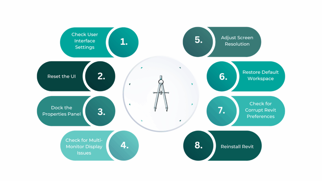
Below is a step-by-step guide to recover the missing Properties Panel in Revit:
- Check User Interface Settings
Sometimes, the Properties Panel is accidentally turned off in the settings. To fix this, go to the View tab in the Ribbon, click on User Interface under the Windows section, and ensure that Properties is checked. You can also utilse the shortcut Ctrl + 1 to instantly toggle the panel on or off.
- Reset the UI (User Interface)
If the panel has moved off-screen or is misplaced, resetting the UI can help. Open the View tab, click on Windows, and select Reset UI. This will restore Revit’s default layout, which should bring back the Properties Panel.
- Dock the Properties Panel
If the Properties Panel is floating or off-screen, you can dock it back to its original position. Click and hold the panel’s title bar, then drag it towards the left or right side of the screen. When a blue highlight appears, release the mouse button to dock the panel in place.
- Check for Multi-Monitor Display Issues
If you are using multiple monitors, the Properties Panel may be off-screen, especially if a monitor was disconnected or turned off. To fix this, disconnect any additional monitors and resize the Revit window to fit your primary screen.
You can also press Windows Key + Shift + Left Arrow or Windows Key + Shift + Right Arrow to move the panel back into view.
- Adjust Screen Resolution
Sometimes, low screen resolution or changes in display settings can cause the Properties Panel to disappear. Right-click on your desktop, open Display settings, and adjust the resolution to the recommended level to fix this. Once adjusted, restart Revit and check if the panel is visible.
- Restore Default Workspace
Switching between workspace profiles can sometimes hide the Properties Panel. To restore it, go to the View tab, click on Windows, and select Restore Default Workspace. This will reset all panels to their default positions.
- Check for Corrupt Revit Preferences
Corrupt preference files can cause interface issues, including the Properties Panel disappearing. To reset your preferences, close Revit and locate the Revit.ini file in the AppData folder. Rename or delete this file (e.g., Revit.ini.old) to reset Revit’s settings to default.
- Reinstall Revit
If none of the above steps work, reinstalling Revit may be the best solution. First, uninstall Revit through the Control Panel or Settings. Then, download the latest version from the Autodesk website and reinstall it. After installation, check if the Properties Panel is back.
Restoring the Properties Panel helps you regain control over your workflow, but another setting that can impact efficiency is Auto Apply.
How to Disable Auto Apply in Revit?
In Revit, the Auto Apply feature automatically updates changes made in the Properties Panel. While this can be useful, there are times when you might want more control, especially when working on complex models or large projects.
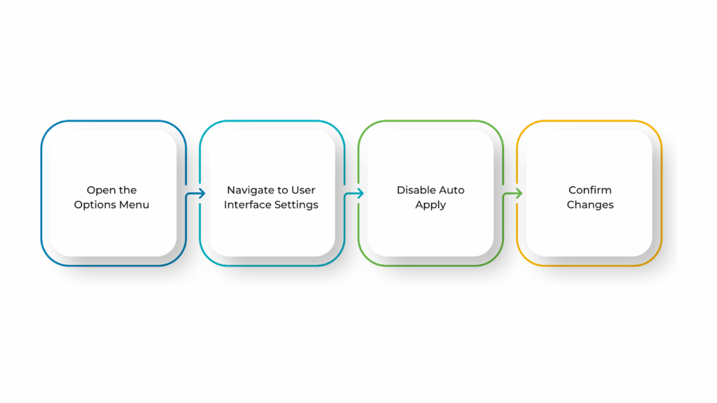
Disabling Auto Apply helps prevent changes from being applied instantly, allowing you to review and adjust your modifications before they take effect. This gives you more flexibility in managing your design. To disable Auto Apply in Revit, follow these steps:
- Open the Options Menu
Click the File tab in the upper left corner of the Revit window. Then, select Options from the dropdown menu to open the Revit Options dialog box.
- Navigate to User Interface Settings
In the Options dialog box, find and click on the User Interface section on the left panel. This section contains various settings related to how Revit’s interface works.
- Disable Auto Apply
Under the Properties section, locate the Auto Apply setting. Uncheck the box next to it to disable the feature. This means that changes will no longer be applied automatically. To confirm, click Apply or OK in the dialog box.
- Confirm Changes
Now that Auto Apply is disabled, you will need to manually click the Apply button in the Properties Panel whenever you make changes. This gives you a chance to review modifications before they are applied to the model.
BIM Supports GREEN EARTH.

Conclusion
Bringing back the Properties Panel in Revit is key to working smoothly. It helps you quickly edit and adjust elements, making changes easier and more precise. Restoring it improves productivity, reduces mistakes, and gives you better control over your design.
You can also customise your workspace by rearranging panels and adjusting settings to keep your tools within reach.
Are you looking for BIM solutions?
BIM ASSOCIATES is your one-stop BIM Solution provider for the Architecture and Structure discipline. Their solutions help clients with better decision-making, cost-saving, efficient construction planning, and green earth initiatives.
You might also like: A Complete Guide to Adding, Customising, and Organising Revit Families.
FAQs (Frequently Asked Questions)
1. How do I get my properties box back in Revit?
Go to the View tab, click User Interface, and ensure Properties is checked. If it’s still missing, press PP on your keyboard or reset Revit’s UI to default by closing and reopening the software.
2. How do I restore view properties in Revit?
Open the View tab, click User Interface, and select Properties. Try dragging it from a collapsed panel or resetting the UI if it’s not visible.
3. How do you bring back the properties browser in Revit?
Go to the View tab, click User Interface, and check Properties. If it doesn’t appear, restart Revit or reset the UI to default settings.