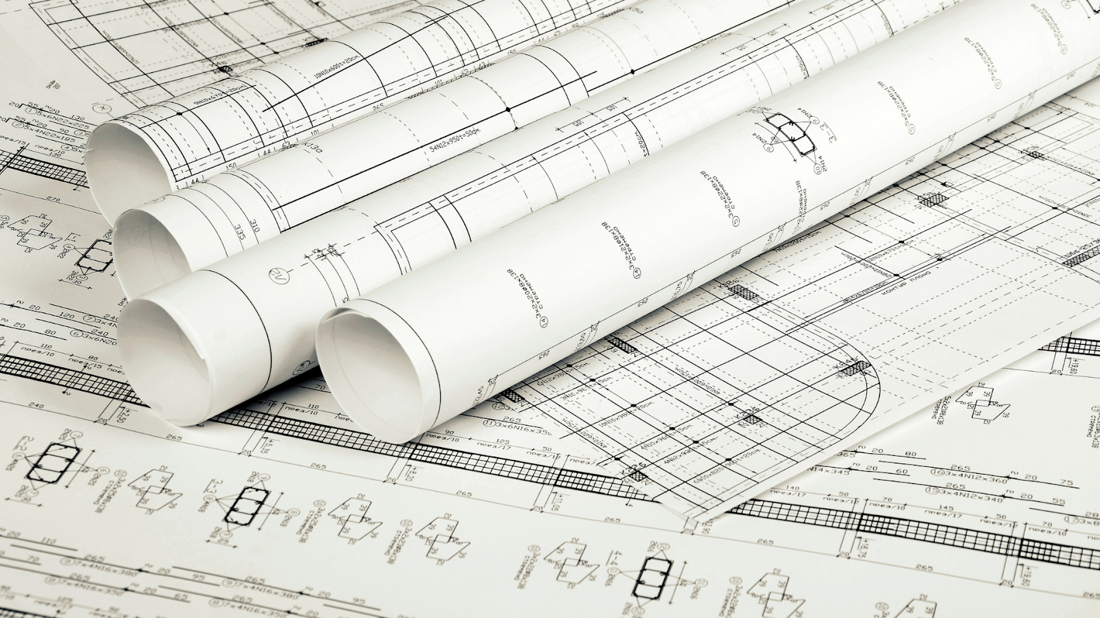
Assembly drawings in construction are essential for showing how different structural, mechanical, and electrical parts fit together to create a complete building or infrastructure project. These detailed drawings give contractors, builders, and engineers clear instructions on installing and assembling each component, ensuring everything fits correctly.
From building foundations to roofing systems, assembly drawings provide a full picture of how each part works together, which prevents mistakes and makes the construction process smoother.
In this article, you’ll learn about assembly drawings, their importance, key parts, and types. In addition, you’ll also explore how to create assembly drawings, the best software tools to use, and the standards that apply to them.
What are Assembly Drawings in Construction?
Assembly drawings are detailed illustrations that provide clear visual instructions for the correct installation, order, and integration of components. This ensures the final building structure matches the design plans. These drawings show the arrangement of walls, beams, foundations, HVAC systems, plumbing, electrical wiring, and other important elements.
They are crucial for preventing errors, reducing confusion, and ensuring all parts work together smoothly and safely, from the start to the finishing touches.
While assembly drawings provide essential direction for construction teams, their true value lies in the wide range of benefits they bring to the entire project.
Benefits of Assembly Drawings
Assembly drawings are very useful in construction because they give clear, detailed instructions on how to put together different parts of a building structure. These drawings help make sure every piece fits/assembles together as planned, which increases the efficiency and accuracy of the project.
By reducing errors and improving communication among teams, assembly drawings offer more than just a visual guide. Assembly drawings in construction offer several key benefits that help improve the overall success of building projects. These benefits include:
- Clear Communication: Assembly drawings provide a clear visual of how different components fit together, making sure everyone—from architects and engineers to contractors understands the project in the same way.
- Reduced Errors: By clearly showing how parts connect, assembly drawings help avoid mistakes and misinterpretations, reducing costly errors and the need for rework.
- Simplified Construction Process: These drawings give step-by-step instructions on how to assemble components, helping teams follow the right order and keep the process moving smoothly, which speeds up construction.
- Improved Coordination: In complex projects, assembly drawings help different teams (like mechanical, electrical, and structural) work together, ensuring their efforts fit together perfectly.
- Material Management: Assembly drawings include details about the materials needed, which prevents delays caused by missing or incorrect materials and makes material ordering more efficient.
- Cost Efficiency: By reducing mistakes and delays, assembly drawings help reduce overall costs. They also allow teams to accurately schedule labour and materials for each project phase.
- Quality Assurance: Assembly drawings ensure the construction follows design specs, maintains high quality, and meets building codes and regulations.
- Easier Troubleshooting and Maintenance: For future repairs or renovations, assembly drawings show how parts are arranged, and systems are connected, making it easier to fix issues or make changes.
- Regulatory Compliance: Assembly drawings help ensure the project meets local building codes, zoning laws, and other regulations, reducing the risk of penalties.
- Enhanced Project Documentation: These drawings become part of the project’s permanent records, which can be helpful for future reference, modifications, or owners who need detailed information about the building.
The benefits of assembly drawings go beyond improving accuracy and coordination; they also shape how construction projects are planned and executed.
Applications of Assembly Drawings in Construction
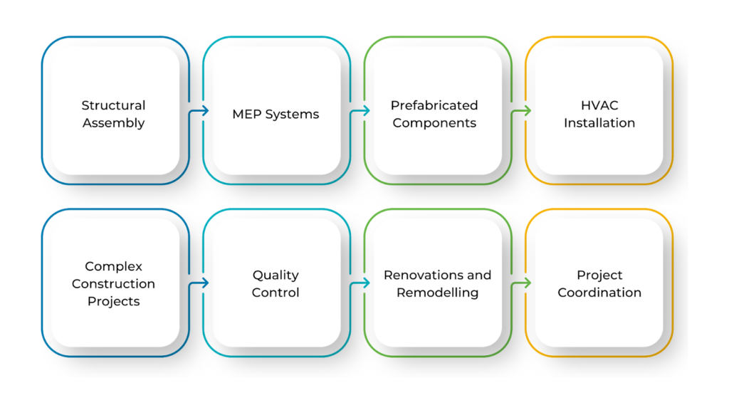
Assembly drawings are often used in steel fabrication, precast concrete installation, modular construction, and MEPF (mechanical, electrical, plumbing and fire) work. These drawings help improve efficiency, reduce material waste, and speed up project completion by simplifying the assembly process. This makes them a crucial part of modern construction.
Below are the applications of assembly drawings:
- Structural Assembly: These drawings show how beams, columns, trusses, and foundations fit together, ensuring the building’s frame is strong and properly built.
- MEPF Systems: They guide the installation of mechanical, electrical, and plumbing (MEPF) systems, ensuring everything is placed correctly and works smoothly within the building.
- Prefabricated Components: For modular construction, assembly drawings help workers assemble pre-made parts on-site quickly and accurately.
- HVAC Installation: These drawings show how to install complex HVAC systems, including ductwork, air handling units, and ventilation systems, in the right order.
- Complex Construction Projects: Large projects like bridges, dams, and skyscrapers use assembly drawings to connect different sections into a complete structure.
- Quality Control: Inspectors use these drawings to check that everything is assembled correctly, ensuring safety and compliance with construction standards.
- Renovations and Remodelling: They help map out how new structures or systems will blend with existing buildings, ensuring everything fits and functions properly.
- Project Coordination: With many teams working on different aspects of a project, assembly drawings serve as a shared reference, keeping everyone aligned.
These drawings are key to accuracy, consistency, and efficiency in construction, helping projects run smoothly from start to finish. However, to fully understand how assembly drawings contribute to construction, it’s important to look at the key elements that make up these detailed images.
Also read: Detailed Drawings in Architectural Design: Types & Creation Process.
Components of Assembly Drawings in Construction
Assembly drawings include important details that provide clear instructions for assembling parts to form a complete structure or system. These drawings help avoid errors and miscommunication by ensuring everyone follows the same guidelines.
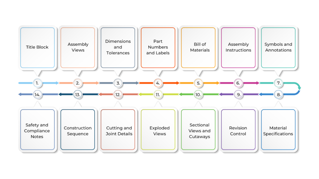
Knowing these elements is essential for ensuring a smooth and efficient assembly process and improving productivity in construction projects. Below are the components of assembly drawings:
- Title Block
The title block contains essential project information such as the drawing title, project name, drawing number, scale, revision history, and the name of the designer or engineer. It helps identify the drawing and serves as a reference throughout the construction process.
- Assembly Views
These are the visual representations of the construction components and how they fit together. Common views include plan views (top-down layout), elevation views (side perspectives), sectional views (cut-through details), and detail views (zoomed-in sections for clarity).
- Dimensions and Tolerances
Accurate dimensions are provided to specify the exact size, placement, and spacing of components. Tolerances indicate the allowable variation in these measurements, ensuring that parts fit together correctly even with slight manufacturing variations.
- Part Numbers and Labels
Each component in the assembly drawing is labelled with a unique part number or identifier. These numbers correspond to the Bill of Materials (BOM) and ensure the correct parts are used during assembly.
- Bill of Materials (BOM)
The BOM includes all components and materials needed for the assembly, along with their quantities, descriptions, and material specifications. It helps procurement teams order the right materials and track their usage during construction.
- Assembly Instructions
These provide specific instructions on how to assemble the components, including the sequence of assembly, fastening methods such as bolting, welding, or gluing, and any special requirements for the process. This ensures the correct order and method for putting parts together.
- Symbols and Annotations
Standardised symbols and annotations are used to represent specific construction elements, such as electrical components, HVAC systems, or plumbing fixtures. These symbols help communicate complex details quickly and clearly. Examples include welding symbols, electrical symbols, and piping symbols.
- Material Specifications
These details outline the types of materials required for each component, such as concrete, steel, or wood, along with any additional material properties like strength, finish, or grade. This ensures that all parts are made from the correct materials that meet the project’s requirements.
- Revision Control
The revision block records all changes made to the assembly drawing throughout the project. This includes any modifications to dimensions, materials, or methods. Tracking revisions ensures the construction team always works with the latest drawing version.
- Sectional Views and Cutaways
These are used to show internal details of components that are not visible in external views. Sectional views provide a clearer understanding of how parts connect or fit together within the overall assembly, such as in walls, foundations, or systems within the building.
- Exploded Views
In complex assemblies, exploded views show how different parts are arranged relative to each other, separated slightly to show the assembly sequence. This is especially useful for understanding how large or intricate systems, such as mechanical equipment or multi-layered structures, should be assembled.
- Cutting and Joint Details
These sections show how different parts are cut, joined, or welded together. They may also specify fasteners, bolts, nuts, and other hardware required for connecting the assembly components.
- Construction Sequence
This component may include a flowchart or diagram that details the correct order of assembly. It ensures that construction proceeds logically and efficiently, minimising delays and preventing mistakes during the building process.
- Safety and Compliance Notes
These are additional instructions or warnings that emphasise safety considerations or compliance with building codes and regulations. They help ensure that the assembly is performed safely and per legal requirements.
Understanding the key components of assembly drawings gives us a clear picture of what information they provide. However, not all assembly drawings are the same.
Ready to simplify your projects and achieve the benefits?
BIM ASSOCIATES is your one-stop BIM Solution provider for Revit Architectural and Structural Solutions. They coordinate with your team to develop, record, and streamline the BIM Revit Model, along with the sheets, Bill of Quantities, Bill of Materials, and clash coordination.
Types of Assembly Drawings in Construction
Assembly drawings come in different types, each serving a specific purpose in the construction process. Some focus on the overall structure, while others provide detailed instructions for smaller components or connections.
The type of assembly drawing used depends on the project’s complexity, materials, and required detail. Understanding these different types of assembly drawings is essential for avoiding mistakes and ensuring a smooth assembly process in any project. Below are the different types of assembly drawings:
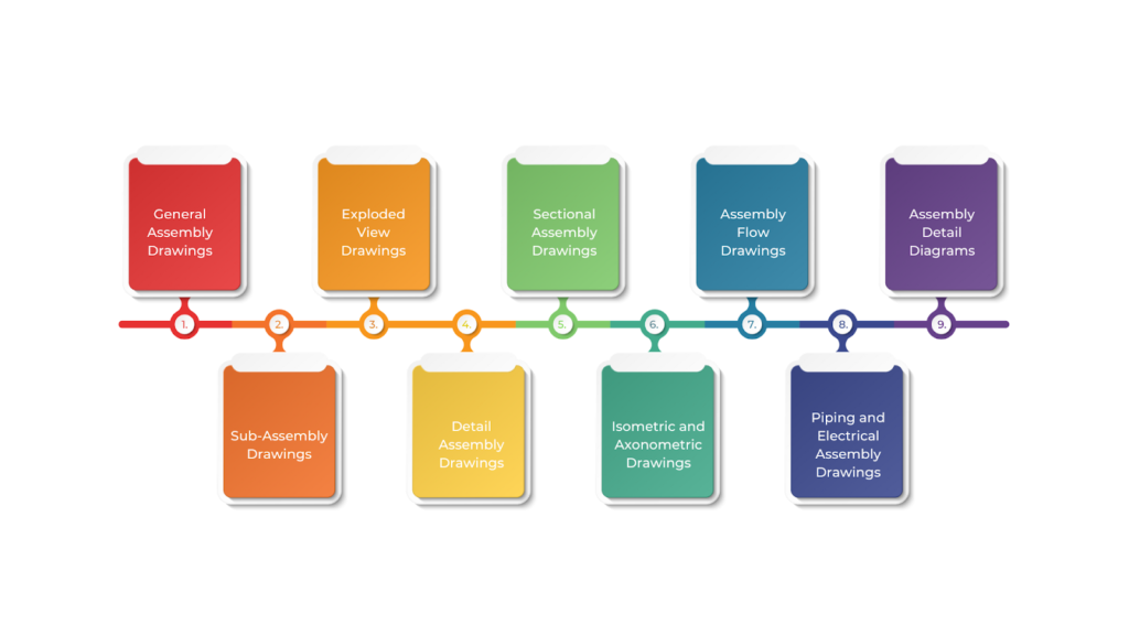
- General Assembly Drawings
These provide a complete overview of an entire assembly, showing how different components fit together. They are commonly used for large structures like buildings, bridges, or mechanical systems. Engineers, architects, and construction teams rely on these drawings to understand the overall arrangement and assembly process.
- Sub-Assembly Drawings
These focus on a specific section of a larger assembly, detailing how smaller parts come together. They are often used by specialists such as electricians or HVAC installers who handle specific elements of a project.
- Exploded View Drawings
These show components slightly separated from each other, providing a clear view of how they fit together. They are particularly useful for complex structures like machinery, bridges, or modular buildings, where understanding individual parts is essential.
- Detail Assembly Drawings
These zoom in on intricate parts of a structure, providing precise details for areas that require accuracy, such as steel joints or plumbing connections. They help ensure clarity in the construction process.
- Sectional Assembly Drawings
These show a “cut-through” view of an assembly, revealing internal features that might not be visible in standard drawings. They are essential for understanding internal components, connections, and safety-critical areas.
- Isometric and Axonometric Drawings
These provide a 3D representation of an assembly, offering a clearer visual of how components fit together. They are commonly used in architectural and structural designs to help clients and non-technical stakeholders understand the final look of a building or system.
- Assembly Flow Drawings
These outline the step-by-step process of assembling a structure and guiding construction teams on the correct sequence of tasks. They help ensure an efficient and logical workflow.
- Piping and Electrical Assembly Drawings
These specialised drawings focus on the installation of piping systems and electrical components. They provide precise placement and connectivity details, making them essential for mechanical and electrical contractors.
- Assembly Detail Diagrams
These show specific components that need extra attention, such as door installations, framing systems, or specialised machine parts. They help clarify complex areas that require a high level of detail.
Each type of assembly drawing plays an important role in ensuring that components are put together correctly, making the construction process more accurate and efficient. Understanding the types of assembly drawings is just the beginning; creating these drawings requires careful planning and attention to detail.
Creation of Assembly Drawings in Construction
Creating assembly drawings is key to making sure construction projects run smoothly. These drawings follow industry standards to help teams communicate clearly and reduce errors during building.
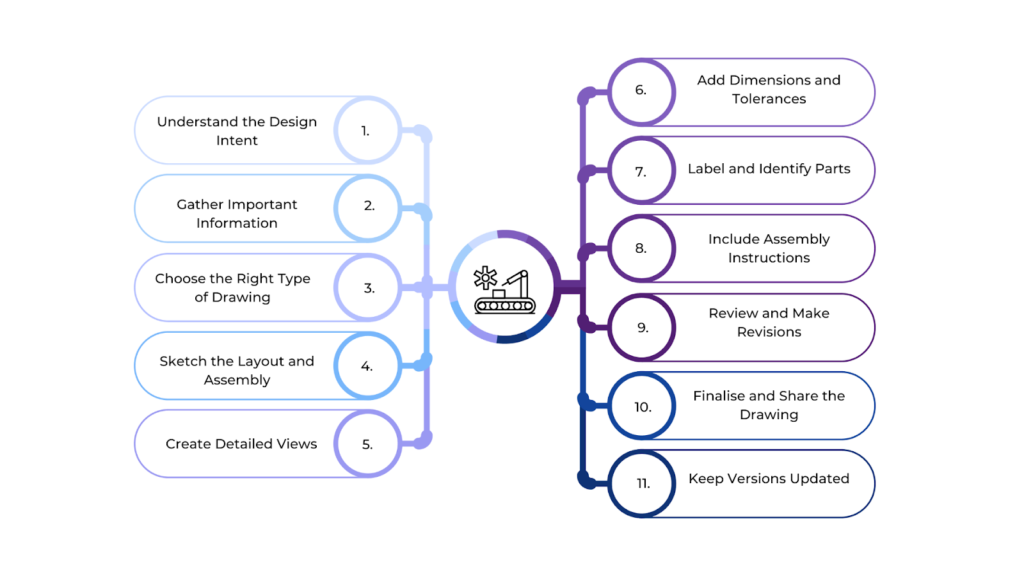
A good assembly drawing improves workflow, keeps teams coordinated, and makes it easier to carry out the project efficiently. Creating these drawings involves several important steps that ensure they are accurate and clear. Below is a step-by-step guide to creating effective assembly drawings:
- Understand the Design Intent
Before creating an assembly drawing, it is important to review architectural plans, structural designs, and engineering specifications. This ensures the drawing aligns with the construction approach, materials, and building codes. Work together with architects, engineers, and other professionals to maintain accuracy and consistency.
- Gather Important Information
An assembly drawing requires precise details about each component, including dimensions, materials, quantities, and specifications. Review previous drawings, such as detail or sub-assembly diagrams, to understand how parts connect. Collecting this information early reduces errors and ensures a smooth workflow.
- Choose the Right Type of Drawing
Select the appropriate type of assembly drawing to enhance clarity. A general assembly drawing provides an overall view, while an exploded view shows how parts fit together. A sectional view reveals hidden details. Choosing the right format improves understanding and communication.
- Sketch the Layout and Assembly
Create a rough layout to visualise the placement of components like beams, walls, doors, and windows. Ensuring proper alignment from the start prevents misinterpretation and simplifies the final drafting process.
- Create Detailed Views
Certain areas, such as joints, fasteners, and internal systems, require additional clarity. Zoomed-in views with appropriate scaling make critical details easily readable and prevent misinterpretation.
- Add Dimensions and Tolerances
Accurate dimensions and tolerances ensure proper fit and assembly. Clearly mark measurements, including length, width, and height, to eliminate guesswork. Geometric Dimensioning and Tolerancing (GD&T) can be used for complex parts.
- Label and Identify Parts
Assign unique part numbers and match them to the Bill of Materials (BOM) for easy identification, sourcing, and tracking. Include material specifications and instructions further to improve efficiency.
- Include Assembly Instructions
Step-by-step instructions guide workers through the assembly process. Clearly outline the order of operations and connection methods, such as welding or bolting, to reduce errors and enhance efficiency.
- Review and Make Revisions
A thorough review ensures accuracy and compliance with industry standards. Check dimensions, labels, and placements to prevent costly errors. Revise and refine the drawing to improve reliability.
- Finalise and Share the Drawing
Once finalised, the drawing should be formatted for clarity and ease of use. Include a title block with project details and revision history. Distribute the drawing in an accessible format, such as CAD, PDF, or print, to ensure smooth communication.
- Keep Versions Updated
Maintain an up-to-date revision history to prevent errors caused by outdated information. Distribute the latest version to relevant teams to ensure accuracy and efficiency during construction.
By following these steps, you ensure that every component is accurately shown, dimensions and tolerances are precise, and the assembly process runs smoothly. The right tools make this easier, helping you create assembly drawings with accuracy and efficiency.
Top Software for Creating Assembly Drawings
Creating accurate assembly drawings in construction requires the right software for precision, efficiency, and teamwork. Modern design tools simplify the process with features like automated dimensions, 3D modelling, clash detection, and real-time collaboration.
These tools help architects, engineers, and builders see how different parts fit together, reducing mistakes and improving workflow. Here’s a list of some of the top software used for creating assembly drawings:
| Software | Key Features |
| AutoCAD | A versatile CAD software offering 2D and 3D drafting tools, ideal for precise assembly drawings and design layouts. |
| Revit | A BIM software for creating parametric 3D models and generating detailed construction documents directly from models. |
| SketchUp | A user-friendly 3D modelling tool perfect for conceptual designs and easy-to-create assembly drawings for small projects. |
| BIM 360 Collaboration Pro | A cloud-based collaboration platform that allows teams to create, share, and manage assembly drawings in real-time. |
While selecting the right software is crucial for creating precise assembly drawings, it’s equally important to follow established standards.
Assembly Drawing Standards in the UK
In the UK, assembly drawing standards help keep construction projects clear, precise, and consistent. They set rules for how components and systems should be shown in drawings, making sure everyone involved understands the details and works smoothly together.
These standards improve communication between architects, engineers, and builders, reducing the risk of errors. By following them, projects can run more efficiently and meet industry regulations. The key aspects of assembly drawings include:
Standardised Representation
Assembly drawings use standard views like plan, elevation, and section to show how parts fit together. Exploded and detailed views make complex areas easier to understand. Different line types help distinguish features—solid lines show visible edges, dashed lines indicate hidden parts, and chain lines mark centrelines.
Dimensioning and Tolerancing
Precise dimensions and tolerances ensure parts fit correctly. Drawings must specify sizes, distances, and positions of components. Tolerances allow slight variations without affecting functionality. Geometric Dimensioning & Tolerancing (GD&T) ensures proper fit and performance.
Part Identification and Numbering
Each part must have a unique number or label for easy identification. A Bill of Materials (BOM) lists all components, including part numbers, quantities, and materials, ensuring proper sourcing and assembly.
Assembly Instructions
Drawings guide the assembly process by specifying the correct order of installation. They also indicate connection methods such as welding, bolting, or other fastening techniques to ensure accuracy and efficiency.
Welding and Fastening Symbols
Standard symbols indicate how parts should be joined. Welding symbols define the type, size, and location of welds, while fastening symbols specify bolts, rivets, screws, or other connectors, ensuring proper assembly.
Material Specifications
Drawings specify required materials, such as steel, wood, or concrete, along with surface treatments like coatings or heat treatments. This ensures durability, functionality, and compliance with project requirements.
Sectional and Detail Views
Sectional views cut through a structure to show internal details, while detail views highlight specific areas that need clarification. These views help in understanding complex assemblies.
Revision Control
A revision block tracks changes with dates, descriptions, and approvals, ensuring that all teams work with the latest information. Approval signatures confirm compliance with design and quality standards.
Compliance with Regulations
Drawings must follow building codes, safety regulations, and environmental standards. They ensure structural integrity, fire safety, accessibility, and sustainable construction practices.
By following these principles, assembly drawings become clear, precise, and effective tools for construction teams.
BIM Supports GREEN EARTH.
Conclusion
Assembly drawings are essential in construction because they provide clear instructions on how different parts of a structure should be put together. They help ensure everything fits correctly, reducing mistakes and improving teamwork among architects, engineers, and builders.
These drawings follow set standards for measurements, materials, and assembly methods, making the construction process smoother while ensuring safety, quality, and compliance with regulations.
Are you looking for BIM solutions?
BIM ASSOCIATES is your one-stop BIM Solution provider for the Architecture and Structure discipline. Their solutions help clients with better decision-making, cost-saving, efficient construction planning, and green earth initiatives.
You might also like: Section Drawings in Architecture: Key Elements, Types, & Best Practices.
FAQs (Frequently Asked Questions)
1. What is a bill of materials (BOM) in an assembly drawing?
A BOM is a list of all parts, materials, and components needed to assemble a product. It includes part names, quantities, and reference numbers.
2. Do assembly drawings include dimensions?
Yes, they often include key dimensions to ensure proper fit and alignment of parts, but they may not show every small detail as part drawings do.
3. How do you read an assembly drawing?
Start by looking at the overall view, then check the part labels, dimensions, and assembly instructions to understand how components fit together.